Chapter: Television and Video Engineering : Monochrome Television Transmitter and Receiver
Video Amplifier Circuit
VIDEO AMPLIFIER CIRCUIT
A
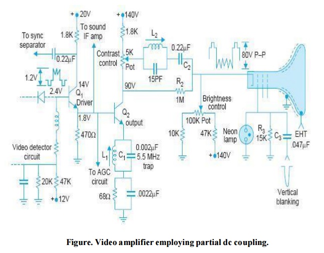
transistorized video amplifier circuit with emitter follower drive and partial
dc coupling is shown in Fig. The salient features of this circuit are :
Signal
from the video detector is dc coupled to the base of Q 1 . This transistor
combines the functions of an emitter follower and CE amplifier. The high input
impedance of emitter follower minimizes loading of the video detector. The sync
circuit is fed from the collector of this transistor, where as signal for the
sound section and AGC circuit is taken from the output of the emitter follower.
The
output from the emitter follower is dc coupled to the base of Q 2 . This is a 5
W power transistor, with a heat-sink mounted on the case. The collector supply
is 140 V, to provide enough voltage swing for the 80 V P-P video signal output.
In the
output circuit of Q 2 , contrast control forms part of the collector load. The
video output signal is coupled by the 0.22 μF (C 2 ) capacitor to the cathode
of picture tube. The partial dc coupling is provided by the 1 M (R 2 ) resistor
connected at the collector of Q 2 .
The
parallel combination of L 1 and C 1 is tuned to resonate at 5.5 MHz to provide
maximum negative feedback to the sound signal. This prevents appearance of
sound signal at the output of video amplifier.
The neon
bulb in the grid circuit provides protection of a spark-gap since the neon bulb
ionizes and shorts to ground with excessive voltage. The ‘spark gaps’ are
employed to protect external receiver circuitry from ‘flash overs’ within the
tube. The accumulation of charge at the various electrodes of the picture tube
results in the appearance of high voltages at the electrodes, which if not
discharged to ground, will do so through sections of the receiver circuitry and
cause damage.
(vi) Note
that dc voltages at the base and emitter of the two transistors have been
suitably set to give desired forward bias.
Vertical
retrace blanking pulses are fed at the grid of the picture tube through C 3,
and the grid-return to ground is provided by R 3 .
Brightness
control. The adjustment of average brightness of the reproduced scene is
carried out by varying the bias potential between cathode and control grid of
the picture tube. In the circuit being considered a 100 KΩ potentiometer is
provided to adjust dc voltage at the cathode.
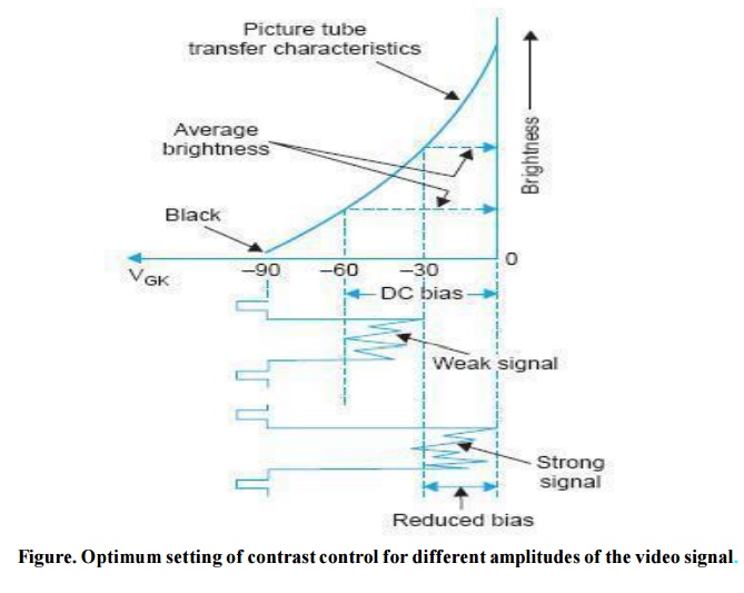
This bias
sets correct operating point for the tube and in conjunction with the video
blanking pulses cuts-off the electron beam at appropriate moments. The setting
of grid bias depends upon the strength of signal being received. A signal of
small amplitude, say from a distant station, requires more fixed negative bias
on the grid than a strong signal. The dependency of picture tube grid bias on
the strength of the arriving signal is illustrated in Fig. For a weak signal,
the bias must be advanced to the point where combination of the relatively
negative blanking voltage plus the tube bias drives the tube into cut-off.
However, with a strong signal the negative grid bias must be reduced, otherwise
some of the picture details are lost. Since the bias of the picture tube may
require an adjustment for different stations, or under certain conditions from
the same station, the brightness control is provided at the front panel of the
receiver. The effects of brightness and contrast controls described earlier
overlap to some extent. If setting of the contrast control is increased so that
the video signal becomes stronger, then the brightness control must be adjusted
to meet the new condition, so that no retrace lines are visible and the picture
does not look milky or washed out. Too small a value of the negative grid bias
allows average illumination of the scene to increase thus making part of the
retrace visible. In addition, the picture assumes a washed out appearance. Too
low a setting of the brightness control, which results in a high negative bias on
the picture tube grid, will cause some of the darker portions of the image to
be eliminated. Besides this overall illumination of the scenes will also
decrease. To correct this latter condition, either the brightness control can
be adjusted or the contrast control setting can be advanced until correct illumination is obtained. If the brightness
control is varied over a wide range the focus of the picture tube may be
affected. However, in the normal range of brightness setting made by the
viewer, changes in focus do not present any problem. It is now apparent that
despite the fact that video signal, as received from any television station,
contains all the information about the background shadings of the scene being
televised, an optimum setting of both contrast control and brightness control
by the viewer is a must to achieve desired results. Many viewers do not get the
best out of their receivers because of incorrect settings of these controls.
However, to ensure that retrace lines are not seen on the screen due to
incorrect setting of either contrast or brightness control, all television
receivers provide blanking pulses on the grid electrode of the picture tube
Related Topics