Chapter: Television and Video Engineering : Monochrome Television Transmitter and Receiver
Television Receiver Antennas
TELEVISION RECEIVER ANTENNAS
For both VHF and UHF television channels, one-half-wave length is a practical size and therefore an ungrounded resonant dipole is the basic antenna often employed for reception of television signals.
The dipole intercepts radiated electromagnetic waves to provide induced signal current in the antenna conductors.
A matched transmission line connects the antenna to the input terminals of the receiver. It may be noted that the signal picked up by the antenna contains both picture and sound signal components.
This is possible, despite the 5.5 MHz separation between the two carriers, because of the large bandwidth of the antenna. In fact a single antenna can be designed to receive signals from several channels that be close to each other.
Antennas for VHF Channels
Although most receivers can produce a picture with sufficient contrast even with a weak signal, but for a picture with no snow and ghosts, the required antenna signal strength lies between 100 and 2000 μV.
Thus, while a half-wave dipole will deliver satisfactory signal for receivers located close to the transmitter, elaborate arrays become necessary for locations far away from the transmitter.
Yagi-Uda Antenna
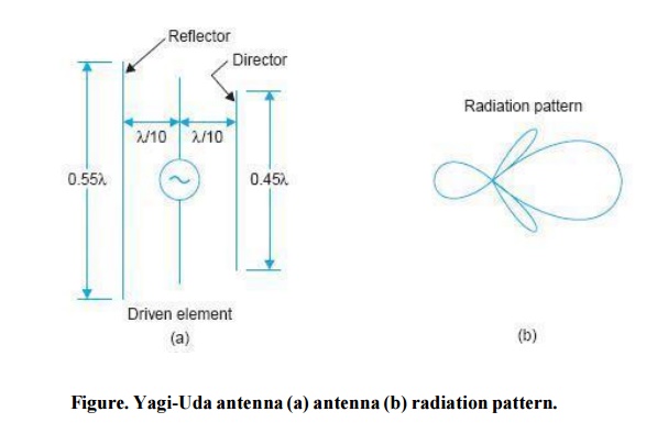
The antenna widel y used with television receivers for locations within 40 to 60 km from the transmitter is the folded dipole with one reflector and one director. This is commonly known as Yagi-Uda or simply Yagi antenna.
The elements of its array as shown in Fig. are arranged collinearly and close together. This antenna provides a gain close to 7 db and is relatively unidirectional as seen from its radiation pattern drawn in Fig.
These characteristics are most suited for reception from television transmitters of moderate capacity. To avoid pick-up from any other side, the back lobe of the radiation pattern can be reduced by bringing the radiators closer to each other.
The resultant improvement in the front to back ratio of the signal pick-up makes the antenna highly directional and thus can be oriented for efficient pick-up from a particular station.
However, bringing the radiators closer has the adverse effect of lowering the input impedance of the array.
As mentioned earlier, it is not necessary to erect a separate antenna for each channel because the resonant circuit formed by the antenna is of low ‘Q’ (quality factor) and as such has a broad band response.
For the lower VHF channels (Band I—channels 2 to 4) the length of the antenna may be computed for a middle value. While this antenna will not give optimum results at other frequencies, the reception will still be quite satisfactory in most cases if the stations are not located far away. Though the antenna length used should be as computed by the usual expression:
Wavelength (λ) = 3 × 10 8 meters,
But in practice it is kept about 6 percent less than the f (Hz) calculated value. This is necessary because the self-capacitance of the antenna alters the current distribution at its ends. The small distance between the two quarter wave rods of the driver, where the lead-in line is connected can be taken as too small and hence neglected. Note that this gap does not affect the current distribution significantly.
Antenna Mounting
The receiving antenna is mounted horizontally for maximum pick-up from the transmitting antenna. As stated earlier, horizontal polarization results in more signal strength, less reflection and reduced ghost images.
The antenna elements are normally made out of 1/4′′ (0.625 cm) to 1/2′′ (1.25 cm) dia aluminum pipes of suitable strength.
The thickness of the pipe should be so chosen that the antenna structure does not get bent or twisted during strong winds or occasional sitting and flying off of birds. A hollow conductor is preferred because on account of skin effect, most of the current flows over the outer surface of the conductor.
The antenna is mounted on a suitable structure at a height around 10 metres above the ground level. This not only insulates it from the ground but results in induction of large signal strength which is free from any interference. The centre of the closed section of the half-wave folded dipole is a point of minimum voltage, allowing direct mounting at this point to the grounded metal mast without shorting the signal voltage.
A necessary precaution while mounting the antenna is that it should be at least two metres away from other antennas and large metal objects. In crowded city areas close to the transmitter, the resultant signal strength from the antenna can sometimes be very low on account of out of phase reflections from surrounding buildings.
In such situations, changing the antenna placement only about a metre horizontally or vertically can make a big difference in the strength of the received signal, because of standing waves set up in such areas that have large conductors nearby. Similarly rotating the antenna can help minimize reception of reflected signals, thereby eliminating the appearance of ghost images.
In areas where several stations are located nearby, antenna rotators are used to turn its direction. These are operated by a motor drive to set the broad side of the antenna for optimum reception from the desired station.
However, in installations where a rotating mechanism is not provided, it is a good practice to connect the antenna to the receiver before it is fixed in place permanently and proceed as detailed below:
Try changing the height of the antenna to obtain maximum signal strength.
Rotate the antenna to check against ghost images and reception of signals from far-off stations.
When more than one station is to be received, the final placement must be a compromise for optimum reception from all the stations in the area. In extreme cases, it may be desirable to erect more than one antenna.
Indoor Antennas In strong signal areas it is sometimes feasible to use indoor antennas provided the receiver is sufficiently sensitive. These antennas come in a variety of shapes.
Most types have selector switches which are used for modifying the response pattern by changing the resonant frequency of the antenna so as to minimize interference and ghost signals.
Generally the switch is rotated with the receiver on, until the most satisfactory picture is obtained on the screen. Almost all types of indoor antennas have telescopic dipole rods both for adjusting the length and also for folding down when not in use.
Fringe Area Antenna
In fringe areas where the signal level is very low, high-gain antenna arrays are needed. The gain of the antenna increases with the number of elements employed. A Yagi antenna with
a large number of directors is commonly used with success in fringe areas for stations in the VHF band.
As already mentioned, a parasitic element resonant at a lower frequency than the driven element will act as a mild reflector, and a shorter parasitic element will act as a mild ‘concentrator’ of radiation.
As a parasitic element is brought closer to the driven element, then regardless of its precise length, it will load the driven element more and therefore reduce its input impedance.
This is perhaps the main reason for invariable use of a folded dipole as the driven element of such an array. A gain of more than 10 db with a forward to back ratio of about 15 is easily obtained with such an antenna. Such high gain combinations are sharply directional and so must be carefully aimed while mounting, otherwise the captured signal will be much lower than it should be.
A typical Yagi antenna for use in fringe areas is shown in Fig.

In such antennas the reflectors are usuall y 5 per cent longer than the dipole and may be spaced from it at 0.15 to 0.25 wavelength depending on design requirements.
Similarly the directors may be 4 per cent shorter than the antenna element, but where broadband characteristics are needed successive directors are usually made shorter (see Fig.) to be resonant for the higher frequency signals of the spectrum.
In some fringe area installations, transistorized booster amplifiers are also used along with the Yagi antenna to improve reception.
These are either connected just close to the antenna or after the transmission line, before the signal is delivered to the receiver.
Yagi Antenna Design
The following expressions can be used as a starting point while designing any Yagi antenna array.
Length of dipole (in metres) ≈143( f is the centre frequency of the channel) f (MHz) Length of reflector (in metres) ≈ 152/f (MHz)
Length of first director (in metres) ≈ 137/f (MHz)
Length of subsequent directors reduces progressively by 2.5 per cent.
Spacing between reflector and dipole = 0.25λ ≈ 75/f (MHz)
Spacing between director and dipole = 0.13λ ≈ 40/f (MHz)
Spacing between director and director = 0.13λ ~ − 39/f (MHz)
The above lengths and spacings are based on elements of 1 to 1.2 cm in diameter. It may be noted that length of the folded dipole is measured from centre of the fold at one end to the centre of the fold at the other end.
It must be remembered that the performance of Yagi arrays can only be assessed if all the characteristics like impedance, gain, directivity and bandwidth are taken into account together. Since there are so many related variables, the dimensions of commercial antennas may differ from those computed with the expressions given above.
However, for single channel antennas the variation is not likely to be much. Figure shows a dimensioned sketch of channel four (61 to 68 MHz) antenna designed for locations not too far from the transmitter. It has an impedance = 40 + j20 Ω, a front to back pick up ratio
= 30 db, and an overall length = 0.37 wavelength.
Multiband Antennas
It is not possible to receive all the channels of lower and higher VHF band with one antenna. The main problem in using one dipole for both the VHF bands is the difficulty of maintaining a broadside response.
This is because the directional pattern of a low-band dipole splits into side lobes at the third and fourth harmonic frequencies in the 174 to 223 MHz band. On the other hand a high-band dipole cut for a half wavelength in the 174 to 233 MHz band is not suitable for the 47 to 68 MHz band because of insufficient signal pick-up at the lower frequencies.
As a result, antennas for both the VHF bands generally use either separate dipoles for each band or a dipole for the lower VHF band modified to provide broadside unidirectional response in the upper VHF band also.
Diplexing of VNF Antennas
When it is required to combine the outputs from the lower and upper VHF band antennas to a common lead-in wire (feeder) it is desirable to employ a filter network that not only matches the signal sources to the common feeder but also isolates the signals in the antennas from each other.
Such a filter arrangement is called a ‘diplexer’. Its circuit with approximate component values for bands I (47 to 68 MHz) and III (174 to 263 MHz) is given in Fig.
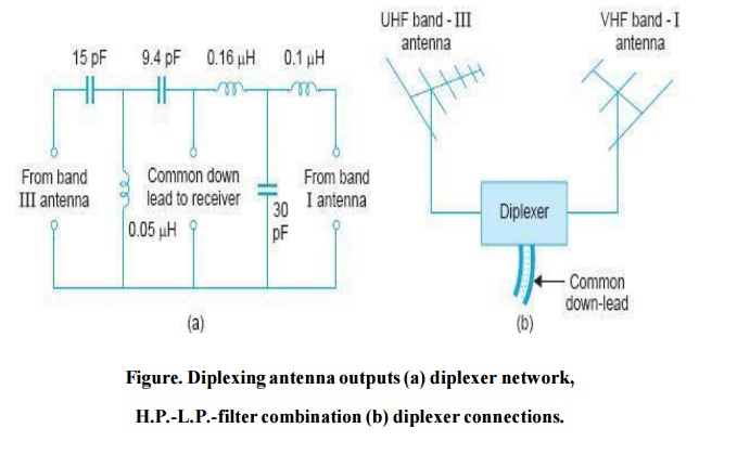
The manner in which it is connected to the two antennas is shown in Fig. Similarly a triplexer filter can be employed when three different antennas are to feed their outputs to a common socket in the receiver.
The combining arrangement can be further modified to connect the output from a UHF antenna to the same feeder line.
Related Topics