Chapter: Television and Video Engineering : Monochrome Television Transmitter and Receiver
RF Tuner
RF TUNER
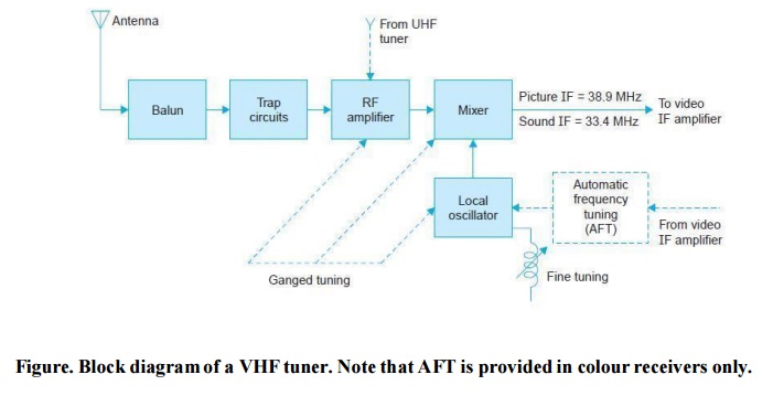
The RF amplifier, the local oscillator and the mixer stages form the RF tuning section. This is commonly known as ‘Tuner’ or ‘Front end’.
A simplified block diagram of the tuner is shown in Fig. It is the same for both monochrome and colour receivers except that automatic frequency tuning is provided in colour receivers only.
The function of the tuner is to select a single channel signal from the many signals picked up by the antenna, amplify it and mix it with the CW (continuous wave) output of the local oscillator to convert the channel frequencies to a band around the intermediate frequency of the receiver.
It is the local oscillator that tunes in the desired station. Its frequency is unique for each channel, which determines the RF signal frequencies to be received and converted to frequencies in the pass-band of the IF section.
TUNER OPERATION
As shown in the tuner block diagram the function of channel selection is accomplished by simultaneously adjusting the tuned circuits of all the three stages that make up the tuner. This means that three or four tuned circuits must be switched while changing channels. The tuned circuits found in both vacuum tube and transistor tuners are as follows:
(i) Input tuned circuit to the RF amplifier
(ii) Output tuned circuit of the RF amplifier
(iii) Input tuned circuit to the mixer
(iv) Local oscillator tuned circuit
In some tuners the mixer input tuned circuit is left out and thus they have only three tuned circuits. Each tuned circuit consists of a coil and a capacitor. The resonating capacitance consists of distributed capacitance of the circuit plus small fixed ceramic capacitors.
The fine tuning control is varied to obtain exact picture and sound intermediate frequencies for which the receiver is designed. The correct setting of the local oscillator frequency is indicated by the best picture obtained on the screen.
Physically, the tuner is wired as a sub-assembly on a separate chassis which is mounted on the main receiver chassis. The IF signal from the tuner is coupled to the first picture IF amplifier through a short coaxial cable. The AGC line and B+ supply are connected from the main chassis to the tuner sub chassis.
The tuner is enclosed in a compact shielded box and all connections are usually brought out at the top of the tuner via feed through capacitors. In tube-type receivers, the filament power to the tuner tubes is also supplied from the common power supply.
Though the principle of selection in television receivers is the same as that in radio receivers the design of the tuner is very different from the heterodyning section of the radio receiver.
This is because of large band width requirements and very high frequencies employed for TV transmission. In fact tuner design techniques differ so much at ultra-high frequencies that all true multichannel receivers employ separate tuners for the VHF and UHF channels. We will confine our discussion to channels with frequencies 47 to 223 MHz in the VHF band (30 to 300 MHz).
FACTORS AFFECTING TUNER DESIGN
The factors that must be considered before attempting to learn details of the tuner circuitry
are:
(a) Choice of IF and Local Oscillator Frequencies
(i) high image rejection ratio,
(ii) reduced local oscillator radiation, (iii) ease of detection and
(iv) good selectivity at the IF stages.
The local oscillator frequency is kept higher than the channel carrier frequency since this results in a relatively narrow oscillator frequency range.
It is then easier to design an oscillator that is stable and delivers almost constant output voltage over its entire frequency range. Intermediate frequencies have been standardized in accordance with the total bandwidth allotted to each channel in different TV systems. In the 625-B monochrome system, the picture IF = 38.9 MHz and sound IF = 33.4 MHz.
Need for an RF Amplifier Stage
In principle an RF amplifier is not necessary and the signal could be fed directly to the tuned input circuit of the mixer as is the normal practice in radio receivers.
However, at very high frequencies the problems of image signals, radiation from the local oscillator through the antenna circuit and conversion loss at the mixer are such that a stage of amplification prior to the mixer is desirable.
Another very important purpose of providing one stage of amplification is to feed enough RF signal into the mixer for a clean picture without snow.
White speckles called snow are caused by excessive noise signals present in the video signal. The mixer circuit generates most of the noise because of heterodyning.
Except in areas very close to the transmitter the signal level is moderate and a low noise RF amplifier stage with a gain of about 25 db becomes necessary to obtain the desired signal-to-noise ratio of 30 : 1.
In fringe areas where the signal level is very low an additional RF amplifier known as booster is often employed to maintain a reasonable signal-to-noise ratio. In all tuner designs the gain of the RF amplifier is controlled by AGC voltage to counter any variations in the input signal to the receiver. A signal level of about 400 µ V at the input to the receiver is considered adequate for a snow free picture.
Coupling Networks
Parallel tuned networks are used to accomplish the desired selectivity in RF and IF sections of the receiver. For minimum power loss the coupling network should match the output impedance of one stage to the input impedance of the following stage.
In circuits employing tubes this does not present any problem because the output and input impedance levels are not very different and the main criterion is to transfer maximum voltage to the next stage.
However, in transistor amplifiers, where the input circuit also consume power, the inter stage coupling network must be designed to transfer maximum power from the output of one stage to the input of the following stage.
The coupling design is further complicated by the fact that in transistors the output and input impedance levels are much different from each other. For example the input impedance of a common base configuration at very high frequencies is only a few tens of ohms, whereas its output impedance is of the order of several tens of kilo-ohms.
UHF TUNERS
There are two types of UHF tuners. In one type the converter section of the UHF tuner converts the incoming signals from the UHF band (470 to 890 MHz) to the VHF band. Usually the UHF channels are converted to VHF channel numbers 5 or 6 and the VHF tuner, in turn, processes these signals in the usual way.
Since the relative positions of video and sound IFs are specified, the converter oscillator of the UHF tuner is tuned to a frequency lower than the incoming UHF signal to take into account the double-heterodyning action involved. In the second type, the UHF signal is heterodyned with local oscillator output to translate the incoming channel directly to the IF band.
The output thus obtained from the UHF tuner is coupled to the VHF tuner, where the RF amplifier and mixer stages operate as IF amplifiers, when the VHF station selector is set to the UHF position. In this position the VHF oscillator is disabled by cutting off its dc suppl y. The RF tuned circuits are also changed to IF tuned circuits. In present day tuners, this type is preferred. Figure illustrates the block schematic of this circuit. Separate antennas are used for VHF and UHF channels.
The UHF tuner does not employ an RF amplifier because the input signal strength being very low is comparable to the noise generated in the RF amplifier. If used it lowers the signal-to-noise ratio and fails to boost the signal level above the noise level.
Therefore, the incoming UHF signal is directl y coupled to the mixer where a diode is used for heterodyning instead of a transistor or a special tube. The reason for using a diode is two-fold. Firstly, the local oscillator output at ultrahigh frequencies is too low to cause effective mixing with an active device whereas it is adequate when a diode is employed. Secondly the noise level with a diode is lower than when an active device is used. Since the diode is a non-linear device it can produce beating of the incoming channel frequencies with the local oscillator frequency to generate side-band frequencies.
Block diagram of a UHF-VHF tuner
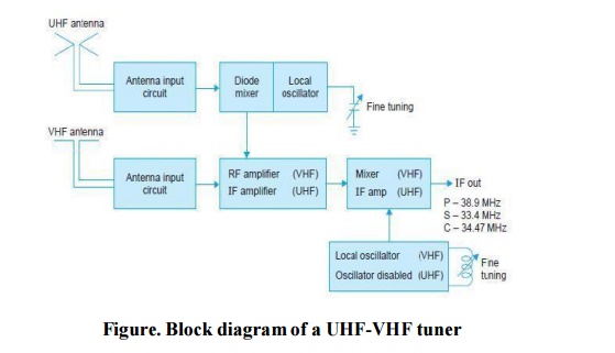
The weak output from the UHF tuner is coupled to the VHF tuner where both the RF amplifier and mixer stages acts as IF amplifiers to boost the signal to the level normally obtained when a VHF channel is tuned.
In conclusion the various functions performed by a television receiver tuner may be summarized as follows:
It selects the desired station and rejects others.
It converts all incoming channel frequencies to a common IF band.
It provides gain to the weak input signal picked up by the antenna. This improves
S/N ratio and reduces snow on the picture.
It isolates the local oscillator from the feeder circuit to prevent undesired radiation through the antenna.
It improves image rejection ratio and thus reduces interference from source operating at frequencies close to the image frequencies of various channels.
It prevents spurious pick-ups from sources which operate in the IF band of the receiver.
It provides matching between the antenna and input circuits of the receiver, thus eliminating the appearance of ghost images on the screen.
It rejects any pick-up from stations operating in the FM band.
It has provision to select any channel out of the various allotted in the VHF and UHF bands for TV transmission.
It has a fine tuning control for accurate setting of the selected station.
Related Topics