Chapter: Television and Video Engineering : Monochrome Television Transmitter and Receiver
Deflection Current Waveforms
DEFLECTION CURRENT WAVEFORMS
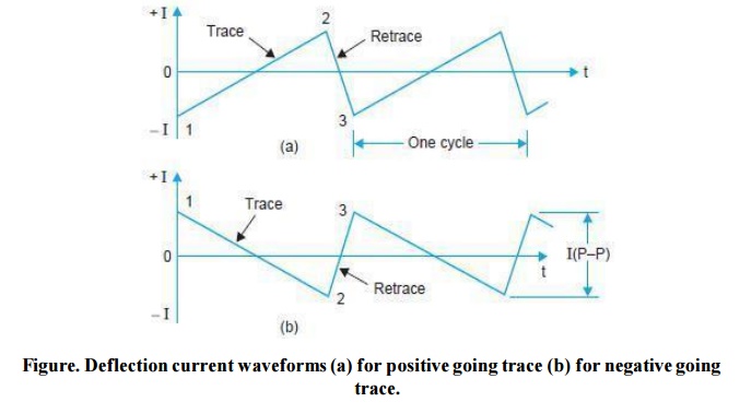
Figure. illustrates the required nature of current in deflection coils. As shown there it has a linear rise in amplitude which will deflect the beam at uniform speed without squeezing or spreading the picture information. At the end of ramp the current amplitude drops sharply for a fast retrace or flyback. Zero amplitude on the sawtooth waveform corresponds to the beam at center of the screen. The peak-to-peak amplitude of the sawtooth wave determines the amount of deflection from the centre. The electron beam is at extreme left (or right) of the raster when the horizontal deflecting sawtooth wave has its positive (or negative) peak. Similarly the beam is at top and bottom for peak amplitudes of the vertical deflection sawtooth wave. The sawtooth waveforms can be positive or negative going, depending on the direction of windings on the yoke for deflecting the beam from left to right and top to bottom. In both cases the trace includes linear rise from start at point 1 to the end at point 2, which is the start of retrace finishing at point 3 for a complete sawtooth cycle.
Driving Voltage Waveform
The current which flows into the horizontal and vertical deflecting coils must have a sawtooth waveform to obtain linear deflection of the beam during trace periods. However, because of inductive nature of the deflecting coils, a modified sawtooth voltage must be applied across the coils to achieve a sawtooth current through them.
To understand this fully, consider the equivalent circuit of a deflecting coil consisting of a resistance R in series with a pure inductance L, where R includes the effect of driving source (internal) resistance.
The voltage drops across R and L for a sawtooth current, when added together would give the voltage waveform that must be applied across the coil. The voltage drop across R has the same sawtooth waveform as that of the current that flows through it.

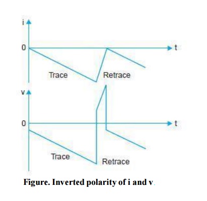
A faster change in i L , produces more self induced voltage v L . Furthermore, for a constant rate of change in i L , the value of v L is constant. As a result, v L in Fig. is at a relatively low level during trace time, but because of fast drop in i L during the retrace period, a sharp voltage peak or spike appears across the coil.
The polarity of the fl yback pulse is opposite to the trace voltage, because i L is then decreasing instead of increasing. Therefore, a sawtooth current in L produces a rectangular voltage.
This means, that to produce a sawtooth current in an inductor, a rectangular voltage should be applied across it. When the voltage drops across R and L are added together, the result is a trapezoidal waveform.
Thus to produce a sawtooth current in a circuit having R and L in series, which in the case.
Related Topics