Chapter: Television and Video Engineering : Monochrome Television Transmitter and Receiver
Television Transmission Antennas
TELEVISION TRANSMISSION ANTENNAS
As already explained, television signals are transmitted by space wave propagation and so the height of antenna must be as high as possible in order to increase the line-of-sight distance.
Horizontal polarization is standard for television broadcasting, as signal to noise ratio is favorable for horizontally polarized waves when antennas are placed quite high above the surface of the earth.
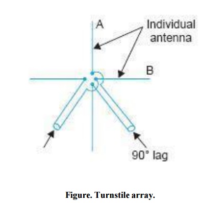
Turnstile Array
To obtain an omnidirectional radiation pattern in the horizontal plane, for equal television signal radiation in all directions, an arrangement known as ‘turnstile array’ is often used.
In this type of antenna two crossed dipoles are used in a turnstile arrangement as shown in Fig. These are fed in quadrature from the same source by means of an extra λ/4 line. Each dipole has a figure of eight pattern in the horizontal plane, but crossed with each other. The resultant field in all directions is equal to the square root of the sum of the squares of fields radiated by each conductor in that direction.
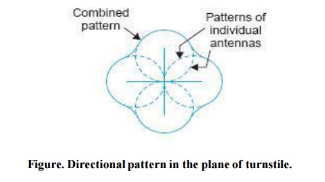
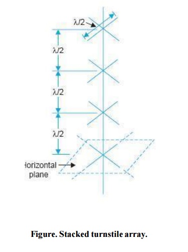
Thus the resultant pattern as shown in Fig. is very nearly circular in the plane of the turnstile antenna. Fig. shows several turnstiles stacked one above the other for vertical directivity.
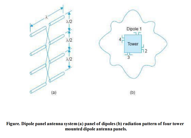
Dipole Panel Antenna System
Another antenna system that is often used for band I and band III transmitters consists of dipole panels mounted on the four sides at the top of the antenna tower as shown in Fig.
Each panel consists of an array of full-wave dipoles mounted in front of reflectors. For obtaining unidirectional pattern the four panels mounted on the four sides of the tower are so fed that the current in each lags behind the previous by 90°.
This is achieved by varying the field cable length by λ/4 to the two alternate panels and by reversal of polarity of the current.
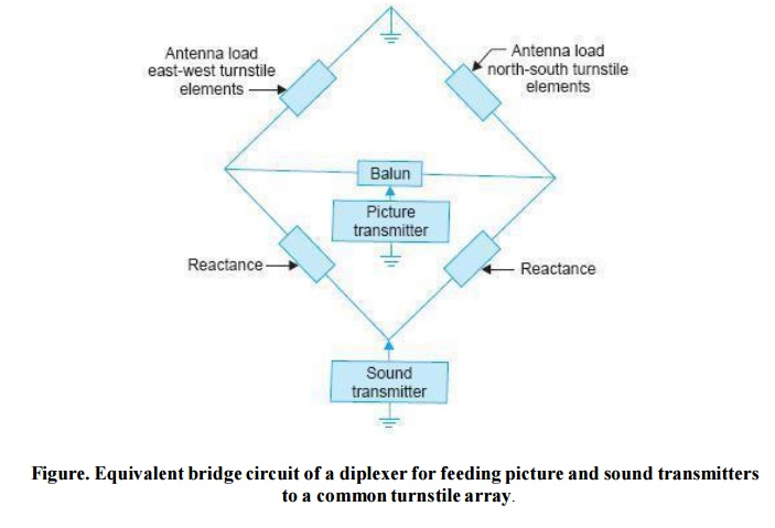
Combining Network
The AM picture signal and FM sound signal from the corresponding transmitters are fed to the same antenna through a balancing unit called diplexer.
As illustrated in Fig. the antenna combining system is a bridge configuration in which first two arms are formed by the two radiators of the turnstile antenna and the other two arms consist of two capacitive reactance.
Under balanced conditions, video and sound signals though radiated by the same antenna, do not interfere with the functioning of the transmitter other than their own.
Related Topics