Chapter: Television and Video Engineering : Monochrome Television Transmitter and Receiver
AGC Noise Cancelling Circuit
AGC NOISE CANCELLING CIRCUIT
Automatic gain control (AGC) circuit varies the gain of a receiver according to the strength of signal picked up by the antenna. The idea is the same as automatic volume control (AVC) in radio receivers.
Useful signal strength at the receiver input terminals may vary from 50 µ V to 0.1 V or more, depending on the channel being received and distance between the receiver and transmitter.
The AGC bias is a dc voltage proportional to the input signal strength. It is obtained by rectifying the video signal as available after the video detector. The AGC bias is used to control the gain of RF and IF stages in the receiver to keep the output at the video detector almost constant despite changes in the input signal to the tuner.
ADVANTAGES OF AGC
The advantages of AGC are:
(a) Intensity and contrast of the picture, once set with manual controls, remain almost constant despite changes in the input signal strength, since the AGC circuit reduces gain of the receiver with increase in input signal strength.
(b) Contrast in the reproduced picture does not change much when the receiver is switched from one station to another.
(c) Amplitude and cross modulation distortion on strong signals is avoided due to reduction
in gain.
(d) AGC also permits increase in gain for weak signals. This is achieved by delaying the application of AGC to the RF amplifier until the signal strength exceeds 150 µ V or so. Therefore the signal to noise ratio remains large even for distant stations. This reduces snow effect in the reproduced picture.
(e) Flutter in the picture due to passing aero planes and other fading effects is reduced.
(f) Sound signal, being a part of the composite video signal, is also controlled by AGC and thus stays constant at the set level.
(g) Separation of sync pulses becomes easy since a constant amplitude video signal Becomes available for the sync separator. AGC does not change the gain in a strictly linear fashion with change in signal strength, but overall control is quite good. For example, with an antenna signal of 200 µ V the combined RF and IF section gain will be 10,000 to deliver 2 V of video signal at the detector output, whereas with an input of 2000 µ V, the gain instead of falling to 1000 to deliver the same output, might attain a value of 1500 to deliver 3 V at the video detector.
Basic AGC Circuit
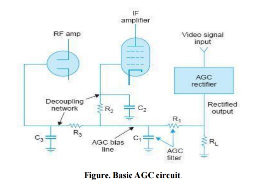
The circuit of Fig. illustrates how AGC bias is developed and fed to RF and IF amplifiers. The video signal on rectification develops a unidirectional voltage across RL. This voltage must be filtered since a steady dc voltage is needed for bias. R1 and C1, with a time constant of about 0.2 seconds, constitute the AGC filter.
A smaller time constant, will fail to remove low frequency variations in the rectified signal, whereas, too large a time constant will not allow the AGC bias to change fast enough when the receiver is tuned to stations having different signal strengths.
In addition, a large time constant will fail to suppress flutter in the picture which occurs on account of unequal signal picked up by the antenna after reflection from the wings of an aero plane flying nearby.
With tubes, a typical AGC filter has 0.1 µ F for C1 and 2 M for R1. For transistors, typical values are 20 k for R1 and 10 µ F for C1. The filtered output voltage across C1 is the source of AGC bias to be distributed by the AGC line.
Each stage controlled by AGC has a return path to the AGC line for bias, and thus the voltage on the AGC line varies the bias of the controlled stages.
Related Topics