Chapter: Computer Graphics and Architecture
Two Dimensional Graphics
TWO DIMENSIONAL GRAPHICS
PREREQUISITE DISCUSSION:
This we discuss about two dimensional concepts and object design.
1. TWO DIMENSIONAL GEOMETRIC TRANSFORMATIONS
CONCEPTS:
Changes in orientations, size and shape are accomplished with geometric transformations that alter the coordinate description of objects. Basic transformation
Translation T(tx, ty)
Translation distances Scale
S(sx,sy)
Scale factors Rotation
R()
Rotation angle
Translation
A translation is applied to an object by representing it along a straight line path from one coordinate location to another adding translation distances, tx, ty to original coordinate position (x,y) to move the point to a new position (x",y") to x’ = x + tx, y’ = y + tyThe translation distance point (tx,ty) is called translation vector or shift vector. Translation equation can be expressed as single matrix equation by using column vectors to represent the coordinate.
Rotations:
A two-dimensional rotation is applied to an object by repositioning it along a circular path on xy plane. To generate a rotation, specify a rotation angle θ and the position (xr,yr) of the rotation point (pivot
point) about which the object is to be rotated.
Scaling :
A scaling transformation alters the size of an object. This operation can be carried out for polygons by multiplying the coordinate values (x,y) to each vertex by scaling factor Sx & Sy to produce the transformed coordinates (x*,y*).
SIGNIFICANCE:
This concept is used to implement a object transformation,resize and rotating in different angle.
2.MATRIX REPRESENTATIONS AND HOMOGENEOUS COORDINATES,COMPOSITE TRANSFORMATIONS
Many graphics applications involve sequences of geometric transformations. Ananimation, for example, might require an object to be translated and rotated at eachincrement of the motion. In order to combine sequence of transformations we haveto eliminate the matrix addition. To achieve this we have represent matrix as 3 X 3instead of 2 X 2 introducing an additional dummy coordinate h. Here points arespecified by three numbers instead of two. This coordinate system is called asHomogeneous coordinate system and it allows to express transformation equationas matrix multiplication
Cartesian coordinate position (x,y) is represented as homogeneous coordinate
triple(x,y,h)
P
![]()
• Represent coordinates as (x,y,h)
• Actual coordinates drawn will be (x/h,y/h)
General Pivot-point Rotation
1.Translate the object so that pivot-position is moved to the coordinate origin
2.Rotate the object about the coordinate origin
Translate the object so that the pivot point is returned to its original position
General fixed point scaling
Translate object so that the fixed point coincides with the coordinate origin
Scale the object with respect to the coordinate origin Use the inverse translation of step 1 to return the object to its original position
3. TWO DIMENSIONAL VIEWING – VIEWING PIPELINE, VIEWING COORDINATE REFERENCEFRAME; WIDOW-TO-VIEWPORT COORDINATE TRANSFORMATION, TWO DIMENSIONAL VIEWING FUNCTIONS;
CONCEPT:
The viewing pipeline
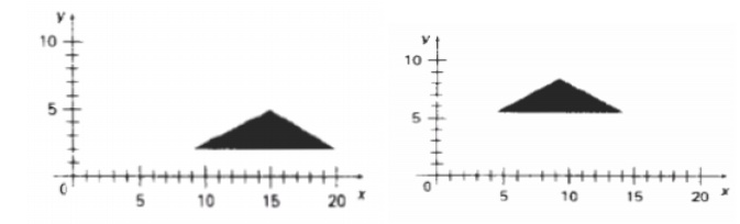
A world coordinate area selected for display is called a window. An area on a display device to which a window is mapped is called a view port. The window defines what is to be viewed the view port defines where it is to be displayed. The mapping of a part of a world coordinate scene to device coordinate is referred to as viewing transformation. The two dimensional viewing transformation is referred to as window to view port transformation of windowing transformation.
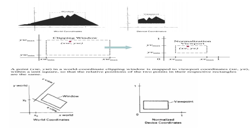
The viewing transformation in several steps, as indicated in Fig. First, we construct the scene in world coordinates using the output primitives. Next to obtain a particular orientation for the window, we can set up a two-dimensional viewing-coordinate system in the world coordinate plane, and define a window in the viewing-coordinate system.
The viewing- coordinate reference frame is used to provide a method for setting up arbitrary orientations for rectangular windows. Once the viewing reference frame is established, we can transform descriptions in world coordinates to viewing coordinates.
We then define a viewport in normalized coordinates (in the range from 0 to 1) and map the viewing-coordinate description of the scene to normalized coordinates. At the final step all parts of the picture that lie outside the viewport are clipped, and the contents of the viewport are transferred to device coordinates.
SIGNIFICANCE:
Changing the position of the viewport, we can view objects at different positions on the display area of an output device.
4. CLIPPINGOPERATIONS – POINT, LINE, AND POLYGON CLIPPING ALGORITHMS
CONCEPT
Point clipping
Line clipping (Straight-line segment)
Area clipping
Curve clipping
Text clipping
Point Clipping
Clip window is a rectangle in standard position. A point P=(x,y) for display, if following inequalities are satisfied: xwmin <= x <= xwmax
ywmin <= y <= ywmax
Line Clipping
A line clipping procedure involves several parts. First we test a given line segment whether it lies completely inside the clipping window. If it does not we try to determine whether it lies completely outside the window . Finally if we can not identify a line as completely inside or completely outside, we perform intersection calculations with one or more clipping boundaries.
All other lines cross one or more clipping boundaries. For a line segment with end points (x1,y1) and (x2,y2) one or both end points outside clipping rectangle, the parametric representation could be used to determine values of u for an intersection with the clipping boundary coordinates.
If the value of u for an intersection with a rectangle boundary edge is outside the range of 0 to 1, the line does not enter the interior of the window at that boundary. If the value of u is within the range from 0 to 1, the line segment does indeed cross into the clipping area. This method can be applied to each clipping boundary edge in to determined whether any part of line segment is to displayed.
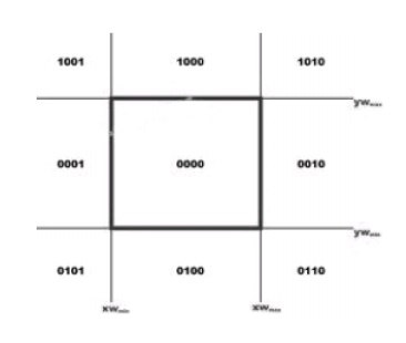
Cohen-Sutherland Line Clipping
This is one of the oldest and most popular line-clipping procedures. The method speeds up the processing of line segments by performing initial tests that reduce the number of intersections that must be calculated. Every line endpoint in a picture is assigned a four digit binary code called a region code that identifies the location of the point relative to the boundaries of the clipping rectangle.
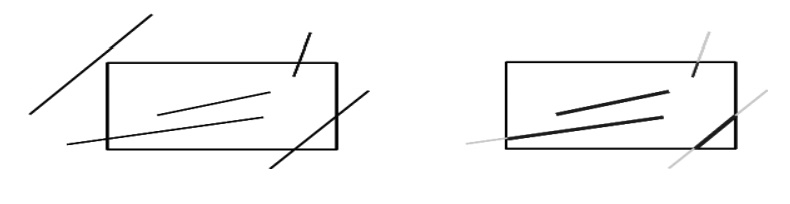
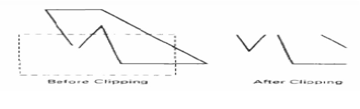
POLYGON CLIPPING
To clip polygons, we need to modify the line-clipping procedures. A polygon boundary processed with a line clipper may be displayed as a series of unconnected line segments (Fig.), depending on the orientation of the polygon to the clipping window.
Sutherland – Hodgeman polygon clipping:
A polygon can be clipped by processing the polygon boundary as a whole against each window edge. This could be accomplished by processing all polygon vertices against each clip rectangle boundary. There are four possible cases when processing vertices in sequence around the perimeter of a polygon. As each point of adjacent polygon vertices is passed to a window boundary clipper, make the following tests:
1. If the first vertex is outside the window boundary and second vertex is inside, both the intersection point of the polygon edge with window boundary and second vertex are added to output vertex list.
2. If both input vertices are inside the window boundary, only the second vertex is added to the output vertex list.
3. If first vertex is inside the window boundary and second vertex is outside only the edge intersection with window boundary is added to output vertex list.
If both input vertices are outside the window boundary nothing is added to the output list.
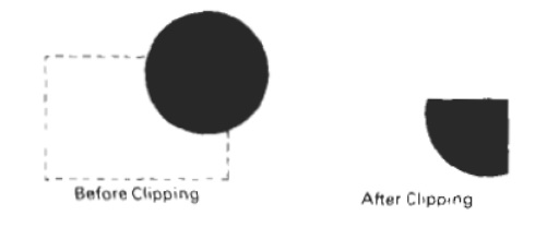
Curve Clipping
Curve-clipping procedures will involve nonlinear equations, and this requires more processing than for objects with linear boundaries. The bounding rectangle for a circle or other curved object can be used first to test for overlap with a rectangular clip window
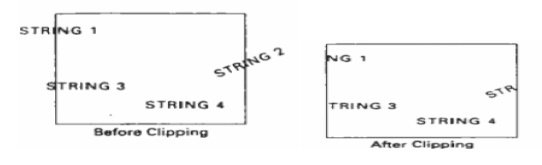
TEXT CLIPPING
An alternative to rejecting an entire character string that overlaps a window boundary is to use the all-or-none character-clippingstrategy. Here we discard only those characters that are not completely inside the window .In this case, the boundary limits of individual characters are compared to the window. Any character that either overlaps or is outside a window boundary is clipped.
Exterior clipping:
Procedure for clipping a picture to the interior of a region by eliminating everything outside the clipping region. By these procedures the inside region of the picture is saved. To clip a picture to the exterior of a specified region. The picture parts to be saved are those that are outside the region. This is called as exterior clipping.
SIGNIFICANCE:
A line clipping procedure involves several parts. First we test a given line segment whether it lies completely inside the clipping window.
APPLICATIONS:
1..Implement clipping algorithms.
2..Implementation of Transformations
Related Topics