Chapter: Graphics and Multimedia : Three-Dimensional Concepts
Three-Dimensional Viewing
THREE-DIMENSIONAL VIEWING
For
three-dimensional applications, First of all, we can view an object from any
spatial position: from the front, from above, or from the back. Or
we could generate a view of what we would see
if we were standing in the middle of a group of objects or inside a single object,
such as a building. Additionally, three-dimensional descriptions of objects
must be projected onto the flat viewing surface of the output device.
VIEWING
COORDINATES
Generating
a view of an object in three dimensions is similar to photographing the object.
We can walk around and take its picture from any angle, at various distances,
and with varying camera orientations. Whatever appears in the viewfinder is
projected onto the flat film surface. The type and size of the camera lens
determines which parts of the scene appear in the final picture.
These
ideas are incorporated into three dimensional graphics packages so that views
of a scene can be generated, given the spatial position, orientation, and
aperture size of the "camera".
Specifying the View Plane
1.
We choose a particular view for a scene by first establishing the
viewing-coordinate system, also
called the view reference coordinate system.
A view plane, or projection plane,
is then set up perpendicular to the viewing z, axis.World-coordinate
positions in the scene are transformed to viewing coordinates, then viewing
coordinates are projected onto the view plane.To establish the
viewing-coordinate reference frame, we first pick a world coordinate position
called the view reference point.
PROJECTIONS
Once
world-coordinate descriptions of the objects in a scene are converted to
viewing coordinates, we can project the three-dimensional objects onto the
triodimensional view plane.
There
are two basic projection methods .
In a
parallel projection, coordinate positions are transformed to the view plane
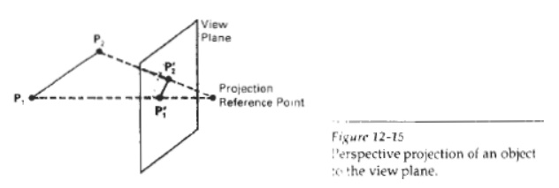
along parallel lines For a perspective projection object positions are
transformed to the view plane a!ong lines that converge to a point called the
projection reference point (or center of projection).
The
projected view of the object is determined by the interjection ofthe projection
lines with the view z. plane.

Parallel Projections
We can specify a parallel
projection with a projection vector that defines the directionfor the
projection lines. When the projection is perpendicular to the view plane, we
have an orthographic parallel projection. Otherwise, we have a oblique parallel
projection.
Orthographic projections are
most often used to produce the front, side, and top views of an object
Perspective projection
n
The center of projection is located at a finite point in three
space.
n
A distant line is displayed smaller than a nearer line of the same
length.
n
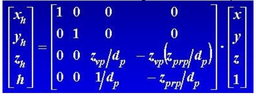
In three-dimensional homogeneous-coordinate representation

When a three-dimensional
obpct is projected onto a view plane using per- hree-Dimensional Viewing
spective transformation equations, any set of parallel lines in the object that
are not parallel to the plane are projected into converging lines.
Parallel Lines that are
parallel to the view plane will be projected as parallel lines.
vanishing point:
o
The point at which a set of projected parallel lines appears to
converge is called a vanishing point.
o Each such set of projected parallel lines will
have a separate vanishing point;
o And in general, a scene can
have any number of vanishing points, depending on howmany sets of parallel
lines there are in the scene.
o The vanishing point for any
set of lines that are parallel to one of the principal axes of an object is
referred to as a principal vanishing point.
o We control the number of
principal vanishing points (one, two, or three) with the orientation of the
projection plane, and perspective projections are accordingly classified as
one-point, two-point, or three-point projections.
THREE-DIMENSIONAL VIEWING FUNCTIONS
Several procedures are
usually provided in a three-dimensional graphics library to enable an
application program to set the parameters for viewing transfonnations.
With parameters spenfied in
world coordinates, elements of the matrix for transforming worldcoordinate
descriptions to the viewing reference frame are calculated using the function evaluateViewOrientationMatrix3
(x0, y0,' Z0, xN, yN, zN, xv, yv, zV, error.,viewMatrix)
1. This function creates the
viewMatrix from input coordinates defining the viewingsystem, 2. Parameters xo,
yo, and z0 specify the origin (view reference point) of the viewing system. 3.
World-coordinate vector defines the normal to the view plane and the direction
of the positive, Three-Dimensional Viewing viewing
axis. 4. And world-coordinate vector (xV, yv, zv) gives the elements of the
view-up vector. The projection of this vector perpendicular to (xN, yN, zN)
estab lishes the direction for the positive y, axis of the viewing system. 6.
An integer error code is generated in parameter error if input values are not
specified correctlyFor example, an error will be generated if we set (XV, YV,
ZV) parallel to (xN, YN, zN)
To specify a second
viewing-coordinate system, we can redefine some or allof the coordinate
parameters and invoke evaluatevieworientationMatrix3 with a new matrix
designation. In this way, we can set up any number of
world-to-viewingcoordinate matrix transformations.
Related Topics