Chapter: Digital Electronics : Sequential Circuits
The Ring Counter
THE RING COUNTER:
In the previous Shift Register tutorial we saw that if we apply a serial data signal to the input of a serial-in to serial-out shift register, the same sequence of data will exit from the last flip-flip in the register chain after a preset number of clock cycles thereby acting as a sort of time delay circuit to the original signal. But what if we were to connect the output of this shift register back to its input so that the output from the last flip-flop, QDbecomes the input of the first flip-flop, DA. We would then have a closed loop circuit that "recirculates" the DATA around a continuous loop for every state of its sequence, and this is the principal operation of a Ring Counter. Then by looping the output back to the input, we can convert a standard shift register into a ring counter. Consider the circuit below.
4-bit Ring Counter
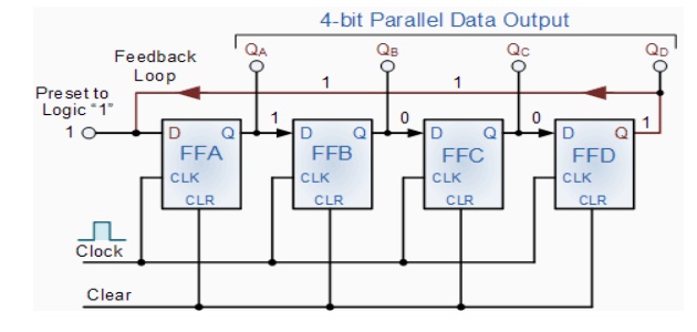
The synchronous Ring Counter example above, is preset so that exactly one data bit in the register is set to logic "1" with all the other bits reset to "0". To achieve this, a "CLEAR" signal is firstly applied to all the flip-flops together in order to "RESET" their outputs to a logic "0" level and then a "PRESET" pulse is applied to the input of the first flip-flop (FFA) before the clock pulses are applied. This then places a single logic "1" value into the circuit of the ring counter . On each successive clock pulse, the counter circulates the same data bit between the four flip-flops over and over again around the "ring" every fourth clock cycle. But in order to cycle the data correctly around the counter we must first "load" the counter with a suitable data pattern as all logic "0"'s or all logic "1"'s outputted at each clock cycle would make the ring counter invalid.
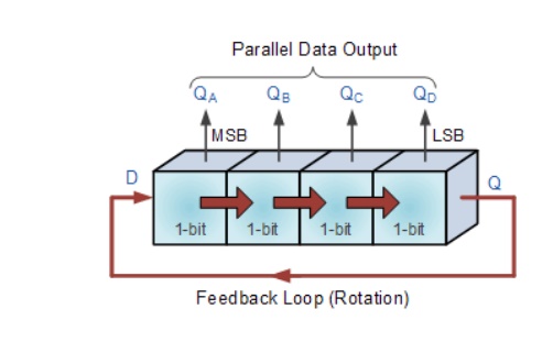
This type of data movement is called "rotation", and like the previous shift register, the effect of the movement of the data bit from left to right through a ring counter .
Rotational Movement of a Ring Counter
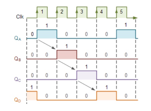
Since the ring counter example shown above has four distinct states, it is also known as a "modulo-4" or "mod-4" counter with each flip-flop output having a frequency value equal to one-fourth or a quarter (1/4) that of the main clock frequency.
The "MODULO" or "MODULUS" of a counter is the number of states the counter counts or sequences through before repeating itself and a ring counter can be made to output any modulo number. A "mod-n" ring counter will require "n" number of flip-flops connected together to circulate a single data bit providing "n" different output states. For example, a mod-8 ring counter requires eight flip-flops and a mod-16 ring counter would require sixteen flip-flops. However, as in our example above, only four of the possible sixteen states are used, making ring counters very inefficient in terms of their output state usage.
Related Topics