Chapter: Digital Electronics : Sequential Circuits
Important Short Questions and Answers: Sequential Circuits
SEQUENTIAL CIRCUITS
1.
Mention any two differences between the edge
triggering and level triggering.
Level Triggering:
1)
The
input signal is sampled when the clock signal is either HIGH or LOW.
2)
It is
sensitive to Glitches.
Example:
Latch.
Edge Triggering:
1)
The
input signal is sampled at the RISING EDGE or FALLING EDGE of the clock signal.
2)
It is
not-sensitive to Glitches.
Example:
Flipflop.
2.
What is meant by programmable counter? Mention
its application.
·
A
counter that divides an input frequency by a number which can be programmed
into decades of synchronous down counters.
·
Decades,
with additional decoding and control logic, give the equivalent of a divide-by N counter system, where N can be made equal to any number.
Appication:
·
Microprocessor.
·
Traffic
light controller.
·
Street
light controller.
3.
Write the characteristic equation of a JK
flip-flop.
The
characteristic equation of a JK flip-flop is given by
Q(next)
= JQ' + K'Q
4.
State the differences between Moore and mealy
state machine.
1)Mealy
Machines tend to have less states
a)
Different
outputs on arcs (n^2) rather than states (n).
2)
Moore
Machines are safer to use
a)
Outputs
change at clock edge (always one cycle later).
b)
In Mealy
machines, input change can cause output change as soon as logic is done
– a big
problem when two machines are interconnected asynchronous feedback. 3) Mealy
Machines react faster to inputs
b)
React in
same cycle – don't need to wait for clock.
c)
In Moore
machines, more logic may be necessary to decode state into outputs – more gate
delays after.
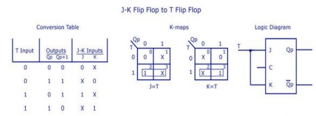
5. Realise T-FF from JK-FF.
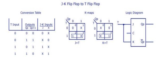
6. Convert JK flip-flop to T flip-flop.
7.
How many flip-flops are required to build a
binary counter that counts from 0 to 1023?
If the number of flip-flops required is n, then
2n-1=1023
n=10 since 210=1024
8.
Compare the logics of synchronous counter and
ripple counter.
Asynchronous counter:
1.
In this
type of counter flipflop are connected in such a way that output of first
flip-flop drives the clock for next flip-flop.
2.
All the
flip-flop are not clocked simultaneously.
3.
Logic
circuit is very simple even for more number of states.
synchronous counter:
1.
In this
type there is no connection between output of first flip-flop and clock input
of the next flip-flop.
2.
All the
flip-flop are clocked simultaneously.
3.
Design
involves complex logic circuit as number of states increases.
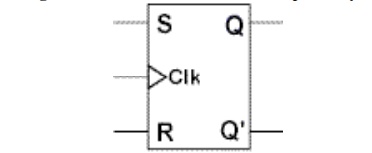
9. Sketch the logic diagram of a clocked SR
flip-flop.
10. How do
you eliminate the race around condition in a JK flip-flop?
·
When the
input to the JK flip-flop is j=1 and k=1, the race around condition occurs, i.e
it occurs when the time period of the clock pulse is greater than the
propagation delay of the flip flop.
·
the
output changes or toggles in a single clock period. If it toggles even number
of times the output is same but if it toggles odd number of times then the
output is complimented.
To avoid
race around condition we cant make the clock pulse smaller than the propagation
delay so we use
1.
Master
slave JK flip flop
2.
Positive
or negative edge triggering
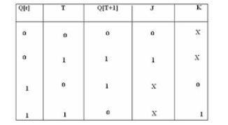
11. Draw the state table and excitation table
of T flip-flop.
12.
A 4-bit binary ripple counter is operated with
clock frequency of 1KHz. What is the output frequency of its third Flip flop?
The
output frequency of third flip-flop is: ½3=1/8KHz.
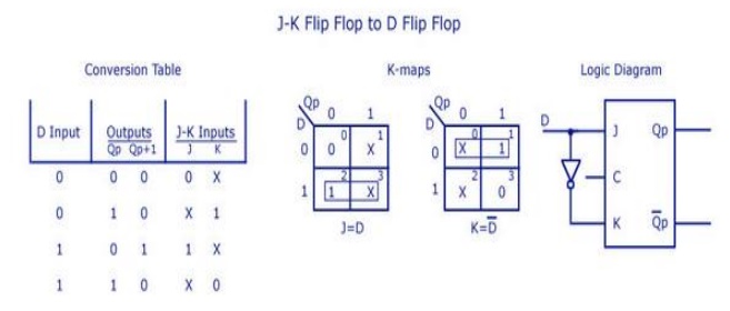
13. Realize JK flip-flop using D flip-flop.
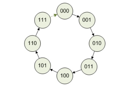
14.
Design a 3-bit ring counter and find the mod of
the designed counter.
15.
Define latches.
Latch is
a simple memory element, which consists of a pair of logic gates with their
inputs and outputs inter connected in a feedback arrangement, which permits a
single bit to be stored.
16.
Write short notes on Digital Clock.
A
digital clock is a simplified logic diagram of a digital clock that displays
seconds, minutes, and hours. First, a 60 Hz sinusoidal ac voltage is converted
to a 60 Hz pulse waveform and divided own to a 1Hz pulse waveform by a
divide-by-60 counter formed by a divide-by-10 counter allowed by a divide-by-6
counter. Both the seconds and minutes counts are also produced by divide-by-60
counters.
Related Topics