Chapter: Electrical machines : Starting and Speed Control of Three Phase Induction Motor
Stator frequency control - Speed control of Three Phase Induction Motors
Stator frequency control
The expression for the synchronous speed indicates that by changing the stator frequency also it can be changed. This can be achieved by using power electronic circuits called inverters which convert dc to ac of desired frequency. Depending on the type of control scheme of the inverter, the ac generated may be variable-frequency-fixed-amplitude or variable-frequency-variable-amplitude type. Power electronic control achieves smooth variation of voltage and frequency of the ac output. This when fed to the machine is capable of running at a controlled speed. However, consider the equation for the induced emf in the induction machine. frequency. Where, N is the number of the turns per phase, φφmm is the peak flux in the air gap and f is the
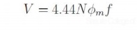
Note that in order to reduce the speed, frequency has to be reduced. If the frequency is reduced while the voltage is kept constant, thereby requiring the amplitude of induced emf to remain the same, flux has to increase. This is not advisable since the machine likely to enter deep saturation. If this is to be avoided, then flux level must be maintained constant which implies that voltage must be reduced along with frequency. The ratio is held constant in order to maintain the flux level for maximum torque capability.
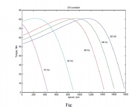
Actually, it is the voltage across the magnetizing branch of the exact equivalent circuit that must be maintained constant, for it is that which determines the induced emf. Under conditions where the stator voltage drop is negligible compared the applied voltage. In this mode of operation, the voltage across the magnetizing inductance in the 'exact' equivalent circuit reduces in amplitude with reduction in frequency and so does the inductive reactance. This implies that the current through the inductance and the flux in the machine remains constant. The speed torque characteristics at any frequency may be estimated as before. There is one curve for every excitation frequency considered corresponding to every value of synchronous speed. The curves are shown below. It may be seen that the maximum torque remains constant.
and f is the frequency of excitation, then E =kf, where k is the constant of proportionality. If = 2π , the developed torque is given by This may be seen mathematically as follows. If E is the voltage across the magnetizing branch
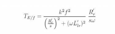
If this equation is differentiated with respect to s and equated to zero to find the slip at maximum into above equation, torque ˆs, we get ˆs = ±R′r/( ωωL′lr). The maximum torque is obtained by substituting this value of frequency. This means that the maximum torque always occurs at a speed lower than It shows that this maximum value is independent of the frequency. Further is independent

synchronous speed by a fixed difference, independent of frequency. The overall effect is an SS apparent shift of the torque-speed characteristic as shown in Fig:
Though this is the aim, E is an internal voltage which is not accessible. It is only the terminal voltage V which we have access to and can control. For a fixed V, E changes with operating slip (rotor branch impedance changes) and further due to the stator impedance drop. Thus if we approximate E/f as V/f, the resulting torque-speed characteristic shown in Fig: is far from desirable.
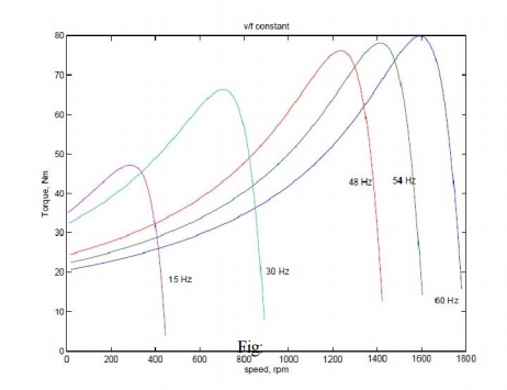
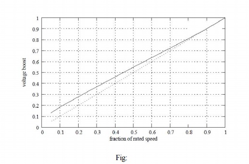
At low frequencies and hence low voltages the curves show a considerable reduction in peak torque. At low frequencies (and hence at low voltages) the drop across the stator impedance prevents sufficient voltage availability. Therefore, in order to maintain sufficient torque at low frequencies, a voltage more than proportional needs to be given at low speeds.
Another component of compensation that needs to be given is due to operating slip. With these two components, therefore, the ratio of applied voltage to frequency is not a constant but is a curve such as that shown in Fig:
With this kind of control, it is possible to get a good starting torque and steady state performance. However, under dynamic conditions, this control is insufficient. Advanced control techniques such as field- oriented control (vector control) or direct torque control (DTC) are necessary.
Related Topics