Chapter: Electrical machines : Starting and Speed Control of Three Phase Induction Motor
Methods of Starting Three Phase Induction Motors
STARTING AND SPEED CONTROL OF THREE PHASE INDUCTION MOTOR
The induction motor is fundamentally a transformer in which the stator is the primary and the rotor is short-circuited secondary. At starting, the voltage induced in the induction motor rotor is maximum (s = 1). Since the rotor impedance is low, the rotor current is excessively large. This large rotor current is reflected in the stator because of transformer action. This results in high starting current (4 to 10 times the full-load current) in the stator at low power factor and consequently the value of starting torque is low. Because of the short duration, this value of large current does not harm the motor if the motor accelerates normally.
However, this large starting current will produce large line-voltage drop. This will adversely affect the operation of other electrical equipment connected to the same lines. Therefore, it is desirable and necessary to reduce the magnitude of stator current at starting and several methods are available for this purpose.
Methods of Starting Three Phase Induction Motors
The method to be employed in starting a given induction motor depends upon the size of the motor and the type of the motor. The common methods used to start induction motors are:
(i) Direct-on-line starting
(ii) Stator resistance starting
(iii) Autotransformer starting
(iv) Star-delta starting
(v) Rotor resistance starting
Methods (i) to (iv) are applicable to both squirrel-cage and slip ring motors. However, method (v) is applicable only to slip ring motors. In practice, any one of the first four methods is used for starting squirrel cage motors, depending upon, the size of the motor. But slip ring motors are invariably started by rotor resistance starting.
Except direct-on-line starting, all other methods of starting squirrel-cage motors employ reduced voltage across motor terminals at starting.
(i) Direct-on-line starting
This method of starting in just what the name implies—the motor is started by connecting it directly to 3-phase supply. The impedance of the motor at standstill is relatively low and when it is directly connected to the supply system, the starting current will be high (4 to 10 times the full-load current) and at a low power factor. Consequently, this method of starting is suitable for relatively small (up to 7.5 kW) machines.
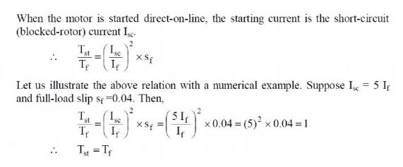
Note that starting current is as large as five times the full-load current but starting torque is just equal to the full-load torque. Therefore, starting current is very high and the starting torque is comparatively low. If this large starting current flows for a long time, it may overheat the motor and damage the insulation.
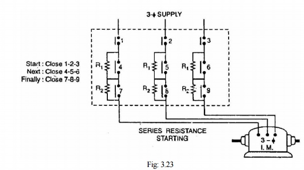
(ii) Stator resistance starting
In this method, external resistances are connected in series with each phase of stator winding during starting. This causes voltage drop across the resistances so that voltage available across motor terminals is reduced and hence the starting current. The starting resistances are gradually cut out in steps (two or more steps) from the stator circuit as the motor picks up speed. When the motor attains rated speed, the resistances are completely cut out and full line voltage is applied to the rotor see Fig: 3.23.
This method suffers from two drawbacks. First, the reduced voltage applied to the motor during the starting period lowers the starting torque and hence increases the accelerating time. Secondly, a lot of power is wasted in the starting resistances.
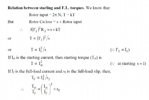
Relation between starting and F.L. torques.
Let V be the rated voltage/phase. If the voltage is reduced by a fraction x by the insertion of resistors in the line, then voltage applied to the motor per phase will be xV.
So,
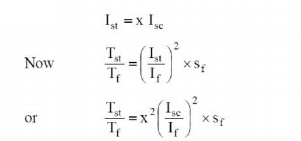
Thus while the starting current reduces by a fraction x of the rated-voltage starting current (Isc), the starting torque is reduced by a fraction x2 of that obtained by direct switching. The reduced voltage applied to the motor during the starting period lowers the starting current but at the same time increases the accelerating time because of the reduced value of the starting torque. Therefore, this method is used for starting small motors only.
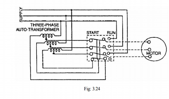
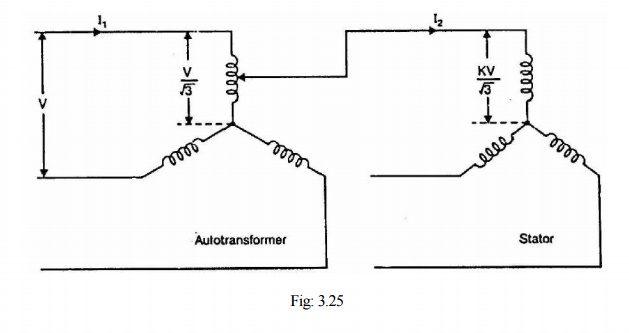
(iii) Autotransformer starting
This method also aims at connecting the induction motor to a reduced supply at starting and then connecting it to the full voltage as the motor picks up sufficient speed. Fig: 3.24 shows the circuit arrangement for autotransformer starting. The tapping on the autotransformer is so set that when it is in the circuit, 65% to 80% of line voltage is applied to the motor.
At the instant of starting, the change-over switch is thrown to "start" position. This puts the autotransformer in the circuit and thus reduced voltage is applied to the circuit. Consequently, starting current is limited to safe value. When the motor attains about 80% of normal speed, the changeover switch is thrown to "run" position. This takes out the autotransformer from the circuit and puts the motor to full line voltage. Autotransformer starting has several advantages viz low power loss, low starting current and less radiated heat. For large machines (over 25 H.P.), this method of starting is often used. This method can be used for both star and delta connected motors.
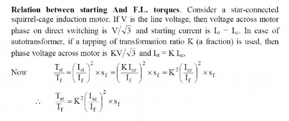
The current taken from the supply or by autotransformer is I1 = KI2 = K2Isc. Note that motor current is K times, the supply line current is K2 times and the starting torque is K2 times the value it would have been on direct-on-line starting.
(iv) Star-delta starting
The stator winding of the motor is designed for delta operation and is connected in star during the starting period. When the machine is up to speed, the connections are changed to delta. The circuit arrangement for star-delta starting is shown in Fig: 3.26.
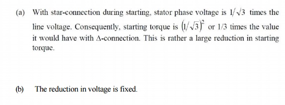
The six leads of the stator windings are connected to the changeover switch as shown. At the instant of starting, the changeover switch is thrown to "Start" position which connects the stator reduces the starting current. When the motor picks up speed, the changeover switch is thrown to "Run" position which connects the stator windings in delta. Now each stator phase gets full line windings in star. Therefore, each stator phase gets V/Ö 3 volts where V is the line voltage. This voltage V. The disadvantages of this method are:
This method of starting is used for medium-size machines (upto about 25 H.P.).
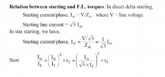
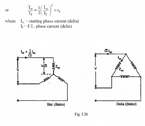
Note that in star-delta starting, the starting line current is reduced to one-third as compared to starting with the winding delta connected. Further, starting torque is reduced to one-third of that obtainable by direct delta starting. This method is cheap but limited to applications where high starting torque is not necessary e.g., machine tools, pumps etc.
Related Topics