Chapter: Electrical machines : Starting and Speed Control of Three Phase Induction Motor
Speed control of Three Phase Induction Motors
Speed control of Three Phase Induction Motors
The induction machine, when operating from mains is essentially a constant speed machine. Many industrial drives, typically for fan or pump applications, have typically constant speed requirements and hence the induction machine is ideally suited for these. However, the induction machine, especially the squirrel cage type, is quite rugged and has a simple construction.
Therefore it is good candidate for variable speed applications if it can be achieved.
Speed control by changing applied voltage
From the torque equation of the induction machine we can see that the torque depends on the square of the applied voltage. The variation of speed torque curves with respect to the applied voltage is shown in Fig:. These curves show that the slip at maximum torque remains same, while the value of stall torque comes down with decrease in applied voltage. The speed range for stable operation remains the same.
Further, we also note that the starting torque is also lower at lower voltages. Thus, even if a given voltage level is sufficient for achieving the running torque, the machine may not start. This method of trying to control the speed is best suited for loads that require very little starting torque, but their torque requirement may increase with speed.
Fig: 3.28 also shows a load torque characteristic — one that is typical of a fan type of load. In a fan (blower) type of load, the variation of torque with speed is such that T∝ ω2. Here one can see that it may be possible to run the motor to lower speeds within the range ns to (1 ˆs) ns. Further, since the load torque at zero speed is zero, the machine can start even at reduced voltages. This will not be possible with constant torque type of loads.
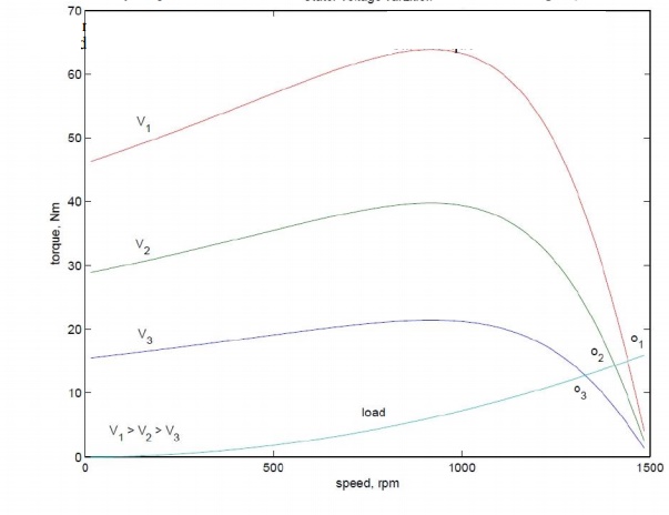
One may note that if the applied voltage is reduced, the voltage across the magnetising branch also comes down. This in turn means that the magnetizing current and hence flux level are reduced. Reduction in the flux level in the machine impairs torque production which is primarily the explanation for Fig: 3.28. If, however, the machine is running under lightly loaded conditions, then operating under rated flux levels is not required. Under such conditions, reduction in magnetizing current improves the power factor of operation. Some amount of energy saving may also be achieved.
Voltage control may be achieved by adding series resistors (a lossy, inefficient proposition), or a series inductor / autotransformer (a bulky solution) or a more modern solution using semiconductor devices. A typical solid state circuit used for this purpose is the AC voltage controller or AC chopper.
Rotor resistance control
The expression for the torque of the induction machine is dependent on the rotor resistance. Further the maximum value is independent of the rotor resistance. The slip at maximum torque is dependent on the rotor resistance. Therefore, we may expect that if the rotor resistance is changed, the maximum torque point shifts to higher slip values, while retaining a constant torque. Fig: 3.29 shows a family of torque-speed characteristic obtained by changing the rotor resistance.
Note that while the maximum torque and synchronous speed remain constant, the slip at which maximum torque occurs increases with increase in rotor resistance, and so does the starting torque. Whether the load is of constant torque type or fan-type, it is evident that the speed control range is more with this method. Further, rotor resistance control could also be used as a means of generating high starting torque.
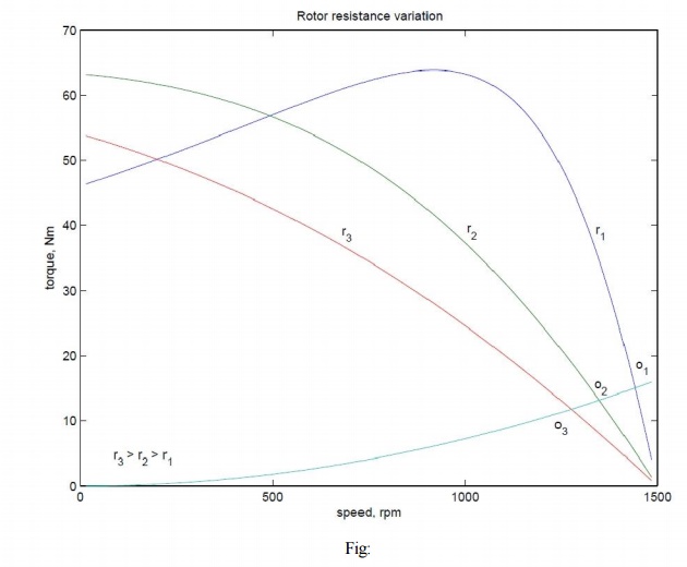
For all its advantages, the scheme has two serious drawbacks. Firstly, in order to vary the rotor resistance, it is necessary to connect external variable resistors (winding resistance itself cannot be changed). This, therefore necessitates a slip-ring machine, since only in that case rotor terminals are available outside. For cage rotor machines, there are no rotor terminals. Secondly, the method is not very efficient since the additional resistance and operation at high slips entails dissipation.
The resistors connected to the slip-ring brushes should have good power dissipation capability. Water based rheostats may be used for this. A 'solid-state' alternative to a rheostat is a chopper controlled resistance where the duty ratio control of the chopper presents a variable resistance load to the rotor of the induction machine.
Cascade control
The power drawn from the rotor terminals could be spent more usefully. Apart from using the heat generated in meaning full ways, the slip ring output could be connected to another induction machine. The stator of the second machine would carry slip frequency currents of the first machine which would generate some useful mechanical power. A still better option would be to mechanically couple the shafts of the two machines together. This sort of a connection is called cascade connection and it gives some measure of speed control.
Let the frequency of supply given to the first machine be f1, its number poles be p1, and its slip of operation be S1. Let f2, p2 and S2 be the corresponding quantities for the second machine. The frequency of currents flowing in the rotor of the first machine and hence in the stator of the second machine is S1 f1. Therefore f2 = S1 f1. Since the machines are coupled at the shaft, the speed of the rotor is common for both. Hence, if n is the speed of the rotor in radians,
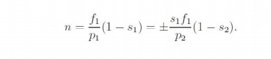
Note that while giving the rotor output of the first machine to the stator of the second, the resultant stator mmf of the second machine may set up an air-gap flux which rotates in the same direction as that of the rotor, or opposes it. This results in values for speed as
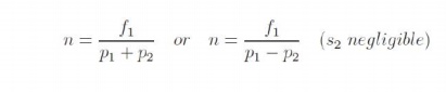
The latter expression is for the case where the second machine is connected in opposite phase sequence to the first. The cascade connected system can therefore run at two possible speeds.
Speed control through rotor terminals can be considered in a much more general way. Consider the induction machine equivalent circuit of Fig: 3.30, where the rotor circuit has been terminated with a voltage source Er.
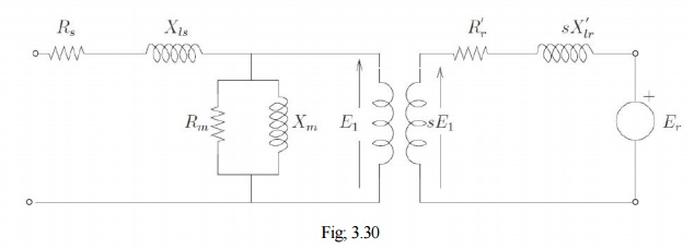
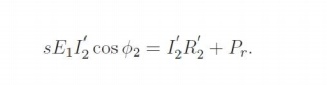
If the rotor terminals are shorted, it behaves like a normal induction machine. This is equivalent to saying that across the rotor terminals a voltage source of zero magnitude is connected. Different situations could then be considered if this voltage source Er had a non-zero magnitude. Let the power consumed by that source be Pr. Then considering the rotor side circuit power dissipation per phase
Clearly now, the value of s can be changed by the value of Pr. for Pr = 0, the machine is like a normal machine with a short circuited rotor. As Pr becomes positive, for all other circuit conditions remaining constant, s increases or in the other words, speed reduces. As Pr becomes negative, the right hand side of the equation and hence the slip decreases. The physical interpretation is that we now have an active source connected on the rotor side which is able to
supply part of the rotor copper losses. When Pr = I′22 R2 the entire copper loss is supplied by the external source. The RHS and hence the slip is zero. This corresponds to operation at
synchronous speed. In general the circuitry connected to the rotor may not be a simple resistor or a machine but a power electronic circuit which can process this power requirement. This circuit may drive a machine or recover power back to the mains. Such circuits are called static Kramer drives.
Pole changing method
Sometimes induction machines have a special stator winding capable of being externally connected to form two different number of pole numbers. Since the synchronous speed of the induction machine is given by ns = fs/p (in rev. /s) where p is the number of pole pairs, this would correspond to changing the synchronous speed. With the slip now corresponding to the new synchronous speed, the operating speed is changed. This method of speed control is a stepped variation and generally restricted to two steps.
If the changes in stator winding connections are made so that the air gap flux remains constant, then at any winding connection, the same maximum torque is achievable. Such winding arrangements are therefore referred to as constant-torque connections. If however such connection changes result in air gap flux changes that are inversely proportional to the synchronous speeds, then such connections are called constant-horsepower type.
The following figure serves to illustrate the basic principle. Consider a magnetic pole structure consisting of four pole faces A, B, C, D as shown in Fig: 3.31.
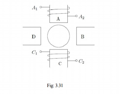
Coils are wound on A & C in the directions shown. The two coils on A & C may be connected in series in two different ways — A2 may be connected to C1 or C2. A1 with the Other terminal at C then form the terminals of the overall combination. Thus two connections result as shown in Fig: 3.32 (a) & (b).
Now, for a given direction of current flow at terminal A1, say into terminal A1, the flux directions within the poles are shown in the figures. In case (a), the flux lines are out of the pole A (seen from the rotor) for and into pole C, thus establishing a two-pole structure. In case (b) however, the flux lines are out of the poles in A & C. The flux lines will be then have to complete the circuit by flowing into the pole structures on the sides. If, when seen from the rotor, the pole emanating flux lines is considered as North Pole and the pole into which they enter is termed as south, then the pole configurations produced by these connections is a two-pole arrangement in Fig: 3.32(a) and a four-pole arrangement in Fig: 3.32 (b).

Thus by changing the terminal connections we get either a two pole air-gap field or a four- pole field. In an induction machine this would correspond to a synchronous speed reduction in half from case (a) to case (b). Further note that irrespective of the connection, the applied voltage is balanced by the series addition of induced emf s in two coils. Therefore the air-gap flux in both cases is the same. Cases (a) and (b) therefore form a pair of constant torque connections.
Consider, on the other hand a connection as shown in the Fig: 3.32 (c). The terminals T1 and T2 are where the input excitation is given. Note that current direction in the coils now resembles that of case (b), and hence this would result in a four-pole structure. However, in Fig: 3.32 (c), there is only one coil induced emf to balance the applied voltage. Therefore flux in case (c) would therefore be halved compared to that of case (b) or case (a), for that matter). Cases (a) and (c) therefore form a pair of constant horse-power connections.
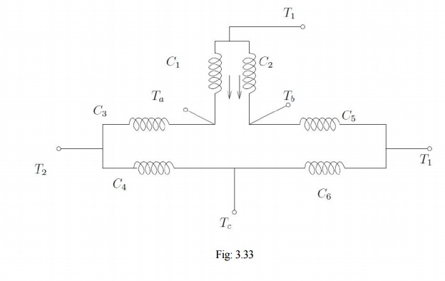
It is important to note that in generating a different pole numbers, the current through one coil (out of two, coil C in this case) is reversed. In the case of a three phase machine, the following example serves to explain this. Let the machine have coils connected as shown [C1 C6] as shown in Fig:
The current directions shown in C1 & C2 correspond to the case where T1, T2, T3 are supplied with three phase excitation and Ta, Tb &Tc are shorted to each other (STAR point). The applied voltage must be balanced by induced emf in one coil only (C1 & C2 are parallel). If however the excitation is given to Ta, Tb &Tc with T1, T2, T3 open, then current through one of the coils (C1 & C2) would reverse. Thus the effective number of poles would increase, thereby bringing down the speed. The other coils also face similar conditions.
Stator frequency control
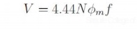
The expression for the synchronous speed indicates that by changing the stator frequency also it can be changed. This can be achieved by using power electronic circuits called inverters which convert dc to ac of desired frequency. Depending on the type of control scheme of the inverter, the ac generated may be variable-frequency-fixed-amplitude or variable-frequency-variable-amplitude type. Power electronic control achieves smooth variation of voltage and frequency of the ac output. This when fed to the machine is capable of running at a controlled speed. However, consider the equation for the induced emf in the induction machine. frequency. Where, N is the number of the turns per phase, φφmm is the peak flux in the air gap and f is the
Note that in order to reduce the speed, frequency has to be reduced. If the frequency is reduced while the voltage is kept constant, thereby requiring the amplitude of induced emf to remain the same, flux has to increase. This is not advisable since the machine likely to enter deep saturation. If this is to be avoided, then flux level must be maintained constant which implies that voltage must be reduced along with frequency. The ratio is held constant in order to maintain the flux level for maximum torque capability.
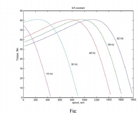
Actually, it is the voltage across the magnetizing branch of the exact equivalent circuit that must be maintained constant, for it is that which determines the induced emf. Under conditions where the stator voltage drop is negligible compared the applied voltage. In this mode of operation, the voltage across the magnetizing inductance in the 'exact' equivalent circuit reduces in amplitude with reduction in frequency and so does the inductive reactance. This implies that the current through the inductance and the flux in the machine remains constant. The speed torque characteristics at any frequency may be estimated as before. There is one curve for every excitation frequency considered corresponding to every value of synchronous speed. The curves are shown below. It may be seen that the maximum torque remains constant.
and f is the frequency of excitation, then E =kf, where k is the constant of proportionality. If = 2π , the developed torque is given by This may be seen mathematically as follows. If E is the voltage across the magnetizing branch
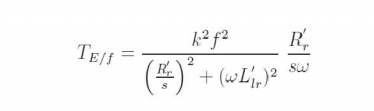
If this equation is differentiated with respect to s and equated to zero to find the slip at maximum into above equation, torque ˆs, we get ˆs = ±R′r/( ωωL′lr). The maximum torque is obtained by substituting this value of frequency. This means that the maximum torque always occurs at a speed lower than It shows that this maximum value is independent of the frequency. Further is independent

synchronous speed by a fixed difference, independent of frequency. The overall effect is an SS apparent shift of the torque-speed characteristic as shown in Fig:
Though this is the aim, E is an internal voltage which is not accessible. It is only the terminal voltage V which we have access to and can control. For a fixed V, E changes with operating slip (rotor branch impedance changes) and further due to the stator impedance drop. Thus if we approximate E/f as V/f, the resulting torque-speed characteristic shown in Fig: is far from desirable.
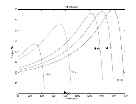
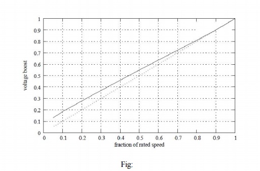
At low frequencies and hence low voltages the curves show a considerable reduction in peak torque. At low frequencies (and hence at low voltages) the drop across the stator impedance prevents sufficient voltage availability. Therefore, in order to maintain sufficient torque at low frequencies, a voltage more than proportional needs to be given at low speeds.
Another component of compensation that needs to be given is due to operating slip. With these two components, therefore, the ratio of applied voltage to frequency is not a constant but is a curve such as that shown in Fig:
With this kind of control, it is possible to get a good starting torque and steady state performance. However, under dynamic conditions, this control is insufficient. Advanced control techniques such as field- oriented control (vector control) or direct torque control (DTC) are necessary.
Related Topics