Chapter: Electrical machines : Starting and Speed Control of Three Phase Induction Motor
Cascade control - Speed control of Three Phase Induction Motors
Cascade control
The power drawn from the rotor terminals could be spent more usefully. Apart from using the heat generated in meaning full ways, the slip ring output could be connected to another induction machine. The stator of the second machine would carry slip frequency currents of the first machine which would generate some useful mechanical power. A still better option would be to mechanically couple the shafts of the two machines together. This sort of a connection is called cascade connection and it gives some measure of speed control.
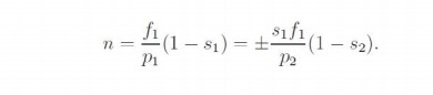
Let the frequency of supply given to the first machine be f1, its number poles be p1, and its slip of operation be S1. Let f2, p2 and S2 be the corresponding quantities for the second machine. The frequency of currents flowing in the rotor of the first machine and hence in the stator of the second machine is S1 f1. Therefore f2 = S1 f1. Since the machines are coupled at the shaft, the speed of the rotor is common for both. Hence, if n is the speed of the rotor in radians,
Note that while giving the rotor output of the first machine to the stator of the second, the resultant stator mmf of the second machine may set up an air-gap flux which rotates in the same direction as that of the rotor, or opposes it. This results in values for speed as
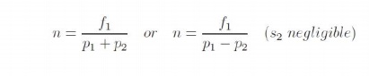
The latter expression is for the case where the second machine is connected in opposite phase sequence to the first. The cascade connected system can therefore run at two possible speeds.
Speed control through rotor terminals can be considered in a much more general way. Consider the induction machine equivalent circuit of Fig: 3.30, where the rotor circuit has been terminated with a voltage source Er.
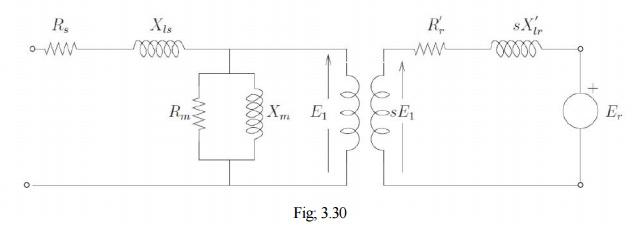
If the rotor terminals are shorted, it behaves like a normal induction machine. This is equivalent to saying that across the rotor terminals a voltage source of zero magnitude is connected. Different situations could then be considered if this voltage source Er had a non-zero magnitude. Let the power consumed by that source be Pr. Then considering the rotor side circuit power dissipation per phase
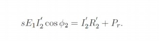
Clearly now, the value of s can be changed by the value of Pr. for Pr = 0, the machine is like a normal machine with a short circuited rotor. As Pr becomes positive, for all other circuit conditions remaining constant, s increases or in the other words, speed reduces. As Pr becomes negative, the right hand side of the equation and hence the slip decreases. The physical interpretation is that we now have an active source connected on the rotor side which is able to
supply part of the rotor copper losses. When Pr = I′22 R2 the entire copper loss is supplied by the external source. The RHS and hence the slip is zero. This corresponds to operation at
synchronous speed. In general the circuitry connected to the rotor may not be a simple resistor or a machine but a power electronic circuit which can process this power requirement. This circuit may drive a machine or recover power back to the mains. Such circuits are called static Kramer drives.
Related Topics