Chapter: Civil : Principles of Solid Mechanics : Torsion
St. Venant’s Formulation (Noncircular Cross Sections)
![]()
![]()
![]()
![]() Torsion
Torsion
Elementary
(Linear) Solution
The general problem of a shaft under torque is
obviously of great practical importance. The linear solution, as presented in a
first course in solid mechanics, assumes that for a circular cross-section,
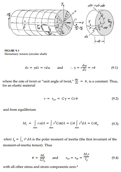
radical lines remain straight when the torque is applied. Thus, as shown in
Figure 9.1, two neighboring cross-sections, dz apart rotate relative to
each other by a small angle of twist dω.
Thus, longitudinal straight lines become helixes at the angle of shear strain, γ,
related to the angle of twist by the circumferential movement:
St. Venant’s
Formulation (Noncircular Cross Sections)
The approach taken by
St. Venant to the torsion problem provides a neat demonstration of the
semi-inverse method of solving the elasticity equations for the displacement
vector field. Although results in closed form can only be found for a few
simple shapes, the St. Venant formulation, because it deals with displacements,
is intuitive and gives physical insight into the complica-tions introduced by
nonconstant axial displacements required to satisfy the boundary conditions for
noncircular cross-sections.**
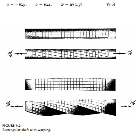
That longitudinal cross-sections, if not circular,
deform or “warp” is shown in Figure 9.2. Assuming the rod is cylindical in the z
direction (and not tapered) and that projections of the cross-section on the xy
plane rotate rigidly at a con-stant rate of twist, θ, St. Venant, pioneering the inverse method, postulated the displacement field
(shown in Figure 9.3):
as the solution (the answer). Thus the warp of the
cross-section, w, is left as an unknown function (i.e., the warping
function) to be adjusted to satisfy the boundary condition dictated by the
shape. In terms of strains, he therefore postulated that:

being the total angle
of twist of the cross-section. Geometric compatibility is automatically
satisfied because this formulation assumes continuous and smooth displacements.
From the constitutive relationships:
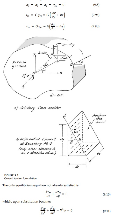
Thus any harmonic
function for the longitudinal displacement or warping is a possible elastic
field solution for the general torsion problem if we can find the shape of the
cross-section where the traction-free boundary condition is satisfied.
The resultant twisting moment on the ends of the rod
is:
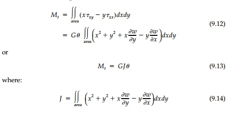
is often called the
“torsional constant” and GJ expresses the “torsional rigidity” of the
bar.
Considering an arbitrary cross-section such as given
in Figure 9.3a, there can be no shear τnt
at the surface. Thus considering an element at any bound-ary point Q,
longitudinal equilibrium requires that:

where dx is negative in Figure 9.3b since a
positive dt causes x to decrease. Therefore, the boundary
condition becomes
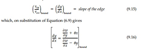
Solutions by St.
Venant
The St. Venant
formulation therefore leads to the search for harmonic functions w(x,y)
that satisfy Equation (9.16). In general this Neumann boundary condi-tion is
difficult to apply especially for nonsymmetric cross-sections where the center
of rotation is not obvious. This illustrates the inherent difficulty, referred
to in Previews, in employing the displacement strategy for elasticity
solu-tions where the boundary conditions involve stresses.
Nevertheless, a few
simple harmonic functions for the warping are man-ageable leading to practical
inverse solutions in closed form. The most obvi-ous is to assume the simplest
solution to the Laplace equation:

and we have a circular shaft and the elementary linear solution already dis-cussed for plane sections is correct. From Equation (9.13), J = Ip = π r4 / 2 and all the standard formulae follow.
b.
w = Kxy
The hyperbolic function, w = Kxy, is harmonic and therefore satisfies the equilibrium requirement of Equation (9.6). The boundary condition [Equation (9.16)] gives: x(K + θ ) dx + y (K - θ ) dy which, when integrated, gives the required boundary shape:

which is somewhat
counterintuitive but will be obvious from the analogies drawn later.
If the ends of the bar
are not restrained from warping, there will be no normal stresses. However, if
one or both ends are restrained such as for a built-in shaft, normal stresses
will be induced similar to those that would result from equal and opposite
bending moments and are, therefore, sometimes called the “bending stresses
induced by torsion.”
Related Topics