Chapter: Civil : Principles of Solid Mechanics : Torsion
Hydrodynamic Analogy and Stress Concentration
Hydrodynamic
Analogy and Stress Concentration
The membrane analogy is the most easily visualized and is, therefore, an excellent heuristic device for all cases. However, at corners or cutouts when there is stress concentration, the accuracy of any laboratory membrane model, such as a soap film experiment, is poor. The conducting sheet analogy mentioned in previews pages, used also to study ground water flow and tempera-ture fields, is much better. An electrically conducting sheet (Telados Paper) cut to the shape of the cross-section transmits a constant current density, i, if a con-stant voltage, V, is applied to its boundary according to the equation, Ō▒»2V = - Žüi, where _, is the uniform resistance of the sheet. While good for experimental analysis, this electrical analogy is no help to the engineer in visualizing areas where the stress field varies quickly. Perhaps hydrodynamic analogies* are best for this purpose. If an ideal fluid (incompressible without viscosity) cir-culates with constant vorticity, Žē, the motion in the x, y plane is described by:

where the velocities in
the x and y direction are given by the derivatives of the stream
function

such that for
equilibrium and compatibility (continuity):

Clearly, from Equation (9.47), the analogy is exact since the boundary is a streamline along which ŽĢ = const. Thus the shear stress in torsion can be visualized as the velocity along a streamline as the fluid circulates around the shape with a magnitude inversely proportional to the distance between streamlines (i.e., proportional to the slope of the velocity hill).
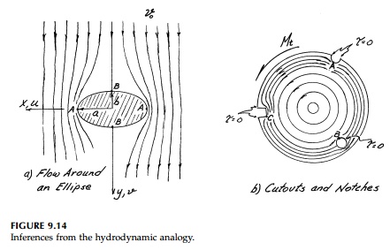
Some immediate results for torsion can be obtained from known solutions in hydrodynamics. For example, an elliptical obstacle in a laminar flow corre-sponds to a hole or cutout in a cross-section resisting torque. Thus, in Figure 9.14a, the streamlines bunch up near the major diameter end points, A, and points B are stagnation points where v = 0 (Žä= 0). At points A where x =+-a, the fluid velocity vy= vo (1 + a/b). Thus for a small hole or cutout in a torsional stress field, as in Figure 9.14b, the shear stress at the root of a small elliptic cutout (point A) would be approximately

where Žäo
is the stress at the point with no disturbance introduced. For a circular hole
or notch such as point A or B, the stress concentration factor is
2. At

a very sharp corner
such as C where a/b theoretically approaches infinity, the
stress reaches yield quickly which explains the problems encountered at the
corner of keyways in drive shafts and in plate girders constructed of flat
plates.*
This question of
determining stress concentration factors is particularly important for
reentrant corners. Structural sections such as angles, wide flange beams, and
channels (Figure 9.11), or rectangular tubes (Figure 9.13) are common in
practice. If corners are perfectly sharp, the shear is theoret-ically infinite,
so rounded corners or fillets are necessary so that the shear can flow smoothly
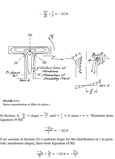
around the corners and the streamlines pile up as little as possible. Take for
example the wide flange shape shown in Figure 9.15. The maximum shears act at
either sections (1), (2), or (3) and equal the slope, which is a maximum at the
boundary. At (1) or (2) there is no shear along lines 1ŌĆ'3 or 2ŌĆ'4 perpendicular
to the contour lines. From the mem-brane analogy

Now from the
hydrodynamic analogy, the quantity of flow through sections A and (1) must be
equal so

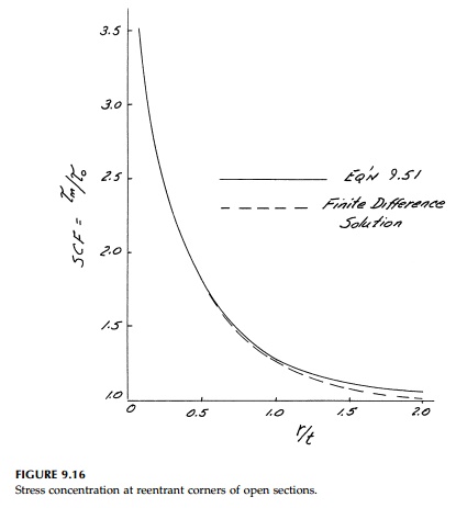
This result is plotted
as Figure 9.16 where Equation (9.51) is seen to be slightly conservative when
compared to results from repeated finite difference solu-tions to PoissonŌĆÖs
equation.

Related Topics