Chapter: Power Electronics : AC to AC Converters
Single phase cycloconverter
Single phase cycloconverter
This
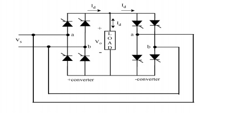
converter consists of back-to-back connection of two full-wave rectifier
circuits. The input voltage, vs is an ac voltage at a frequency,
For easy understanding assume that all the thyristors are fired firing angle,
i.e. thyristors act like diodes. Note that the firing angles are named as P for the positive converter and
for the negative converter. Consider the operation of the cycloconverter to get
one-fourth of the input frequency at the output. For the first two cycles of
vs, the positive converter operates supplying current to the load. It rectifies
the input voltage; therefore, the load sees 4 positive half cycles. In the next
two cycles, the negative converter operates supplying current to the load in
the reverse direction. The current waveforms are not shown in the figures
because the resistive load.current will have the same waveform as
the voltage but only scaled by the resistance. Note that when one of the
converters operates the other one is disabled, so that there is no current
circulating between the two rectifiers
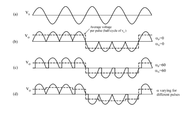
The
frequency of the output voltage, vo in Fig. 3b is 4 times less than that of vs,
the input voltage, i.e. fo/fi=1/4. Thus, this is a step-down cycloconverter. On
the other hand, cycloconverters that have fo/fi>1 frequency relation are
called step-up cycloconverters. Note that step-down cycloconverters are more
widely used than the step-up ones.
The
frequency of vo can be changed by varying the number of cycles the positive and
the negative converters work. It can only change as integer multiples of fi in
1f-1f cycloconverters.
With the
above operation, the 1f-1f cycloconverter can only supply a certain voltage at
a certain firing angle a. The dc output of each rectifier is:
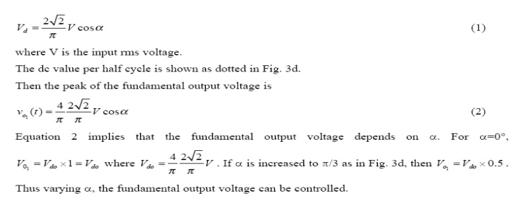
Thus
varying a, the fundamental output voltage can be controlled.
Constant
a operation gives a crude output waveform with rich harmonic content. The
dotted lines in Fig. 3b and c show a square wave. If the square wave can be
modified to look more like a sine wave, the harmonics would be reduced. For
this reason a is modulated as shown in Fig. 3d. Now, the six-stepped dotted
line is more like a sinewave with fewer harmonics. The more pulses there are
with different a's, the less are the harmonics.
Related Topics