Chapter: Power Electronics : AC to AC Converters
Matrix converter - cycloconverters

Matrix converter
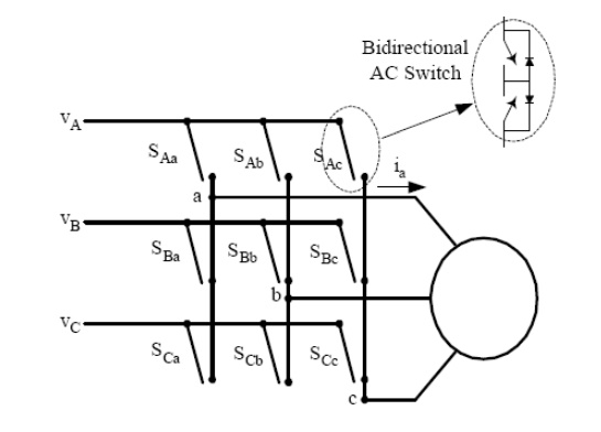
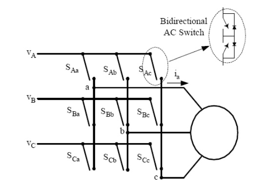
The matrix converter is a fairly new converter topology, which was first proposed in the beginning of the 1980s. A matrix converter consists of a matrix of 9 switches connecting the three input phases to the three output phases directly as shown in Fig. 12. Any input phase can be connected to any output phase at any time depending on the control. However, no two switches from the same phase should be on at the same time, otherwise this will cause a short circuit of the input phases. These converters are usually controlled by PWM to produce three-phase variable voltages at variable frequency.

This direct frequency changer is not commonly used because of the high device count, i.e. 18 switches compared to 12 of a dc link rectifier-inverter system. However, the devices used are smaller because of their shorter ON time compared to the latter.
1. Single-Phase to Three-Phase (1f-3f) Cycloconverters:
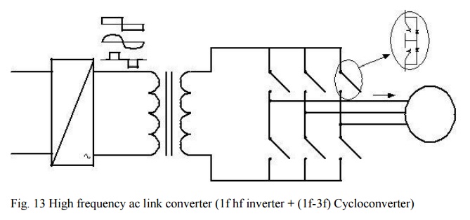
Recently, with the decrease in the size and the price of power electronics switches, single-phase to three-phase cycloconverters (1f-3f) started drawing more research interest. Usually, an H-bridge inverter produces a high frequency single-phase voltage waveform, which is fed to the cycloconverter either through a high frequency transformer or not. If a transformer is used, it isolates the inverter from the cycloconverter. In addition to this, additional taps from the transformer can be used to power other converters producing a high frequency ac link. The single-phase high frequency ac (hfac) voltage can be either sinusoidal or trapezoidal. There might be zero voltage intervals for control purposes or zero voltage commutation. Fig. 13 shows the circuit diagram of a typical hfac link converter. These converters are not commercially available yet. They are in the research state.
Among several kinds, only two of them will be addressed here:
2. Integral Pulse Modulated (1f-3f) Cycloconverters
The input to these cycloconverters is single-phase high frequency sinusoidal or square waveforms with or without zero voltage gaps. Every half-cycle of the input signal, the control for each phase decides if it needs a positive pulse or a negative pulse using integral pulse modulation. For integral pulse modulation, the command signal and the output phase voltage are integrated and the latter result is subtracted from the former. For a positive difference, a negative pulse is required, and vice versa for the negative difference. For the positive (negative) input half-cycle, if a positive pulse is required, the upper (lower) switch is turned on; otherwise, the lower (upper) switch is turned on.
Therefore, the three-phase output voltage consists of positive and negative half-cycle pulses of the input voltage. Note that this converter can only work at output frequencies which are multiples of the input frequency.

3. Phase-Controlled (1f-3f) Cycloconverter
This cycloconverter converts the single-phase high frequency sinusoidal or square wave voltage into three-phase voltages using the previously explained phase control principles. The voltage command is compared to a sawtooth waveform to find the firing instant of the switches. Depending on the polarity of the current and the input voltage, the next switch to be turned on is determined. Compared to the previous one, this converter has more complex control but it can work at any frequency.
Related Topics