Chapter: Power Electronics : AC to AC Converters
AC voltage control techniques
AC voltage control techniques
There are two different types of thyristor control used in practice to control the ac power flow
•On-Off control
•Phase control
These are the two ac output voltage control techniques.
In On-Off control technique Thyristors are used as switches to connect the load circuit to the ac supply (source) for a few cycles of the input ac supply and then to disconnect it for few input cycles. The Thyristors thus act as a high speed contactor (or high speed ac switch).
1. PHASE CONTROL
In phase control the Thyristors are used as switches to connect the load circuit to the input ac supply, for a part of every input cycle. That is the ac supply voltage is chopped using Thyristors during a part of each input cycle. The thyristor switch is turned on for a part of every half cycle, so that input supply voltage appears across the load and then turned off during the remaining part of input half cycle to disconnect the ac supply from the load.
By controlling the phase angle or the trigger angle „α‟ (delay angle), the output RMS voltage across the load can be controlled.
The trigger delay angle „α‟ is defined as the phase angle (the value of ωt) at which the thyristor turns on and the load current begins to flow. Thyristor ac voltage controllers use ac line commutation or ac phase commutation. Thyristors in ac voltage controllers are line commutated (phase commutated) since the input supply is ac. When the input ac voltage reverses and becomes negative during the negative half cycle the current flowing through the conducting thyristor decreases and falls to zero. Thus the ON thyristor naturally turns off, when the device current falls to zero.
Phase control Thyristors which are relatively inexpensive, converter grade Thyristors which are slower than fast switching inverter grade Thyristors are normally used. For applications upto 400Hz, if Triacs are available to meet the voltage and current ratings of a particular application, Triacs are more commonly used.Due to ac line commutation or natural commutation, there is no need of extra commutation circuitry or components and the circuits for ac voltage controllers are very simple.
Due to the nature of the output waveforms, the analysis, derivations of expressions for performance parameters are not simple, especially for the phase controlled ac voltage controllers with RL load. But however most of the practical loads are of the RL type and hence RL load should be considered in the analysis and design of ac voltage controller circuits.
2. PRINCIPLE OF ON-OFF CONTROL TECHNIQUE
(INTEGRALCYCLECONTROL)
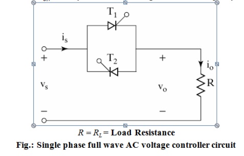
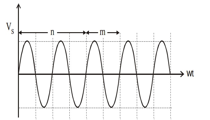
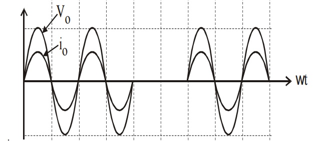
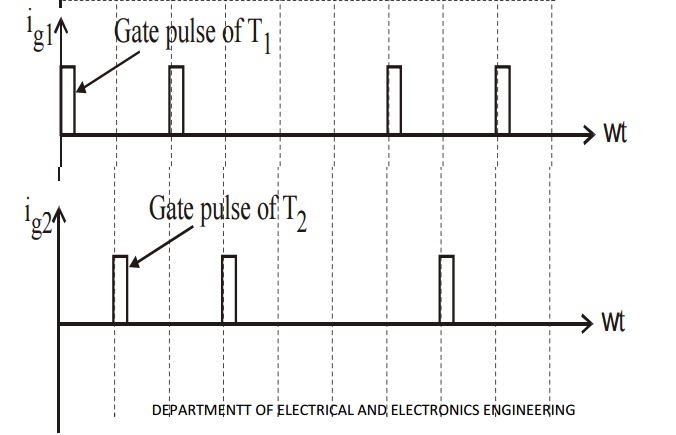
The basic principle o on-off control technique is explained with reference to a single phase full wave ac voltage controller circuit shown below. The thyristor switches T1 and T2 are turned on by applying appropriate gate trigger pulse to connect the input ac supply to the load for ‘n’ number of input cycle during the time interval tON. The thyristor switches T1 and T2 are turned off by blocking the gate trigger pulse for ‘m’ number of input cycles during the interval tOFF. The ac controller ON tome tON usually consists of an integral number of input cycles.
Related Topics