Chapter: Control Systems : Systems and their Representation
Signal Flow Graph Representation
Signal Flow Graph Representation
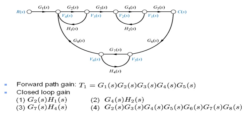
Signal Flow Graph Representation of a system obtained from the equations, which shows the flow of the signal
Signal flow graph
A signal flow graph is a diagram that represents a set of simultaneous linear algebraic equations. By taking Laplace transfer, the time domain differential equations governing a control system can be transferred to a set of algebraic equation in s-domain. A signal-flow graph consists of a network in which nodes are connected by directed branches. It depicts the flow of signals from one point of a system to another and gives the relationships among the signals.
Basic Elements of a Signal flow graph
Node - a point representing a signal or variable.
Branch – unidirectional line segment joining two nodes.
Path – a branch or a continuous sequence of branches that can be traversed from one node to another node.
Loop – a closed path that originates and terminates on the same node and along the path no node is met twice.
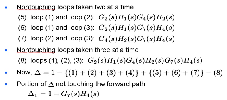
Nontouching loops – two loops are said to be nontouching if they do not have a common node.
Mason’s gain formula
The relationship between an input variable and an output variable of signal flow graph is given by the net gain between the input and the output nodes is known as overall gain of the system. Mason‗s gain rule for the determination of the overall system gain is given below.

Where M= gain between Xin and Xout
Xout =output node variable
Xin= input node variable
N = total number of forward paths
Pk= path gain of the kth forward path
∆=1-(sum of loop gains of all individual loop) + (sum of gain product of all possible combinations of two nontouching loops) – (sum of gain products of all possible combination of three nontouching loops)
Problem


Related Topics