Chapter: Control Systems : Systems and their Representation
Modeling of electrical system
Modeling of electrical system
Electrical circuits involving resistors, capacitors and inductors are considered. The behaviour of such systems is governed by Ohm’s law and Kirchhoff’s laws.
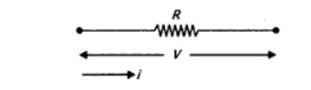
Resistor: Consider a resistance of ‘R’ Ω carrying current ‘I’ Amps as shown in Fig (a), then the voltage drop across it is v = R I
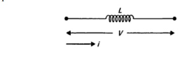
Inductor: Consider an inductor ― L’ H carrying current ’i ’ Amps as shown in Fig (a), then the voltage drop across it can be written as v = L di/dt
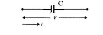
Capacitor: Consider a capacitor ’C’ F carrying current ’i ’ Amps as shown in Fig (a), then the voltage drop across it can be written as v = (1/C)∫ i dt
Steps for modeling of electrical system
o Apply Kirchhoff‗s voltage law or Kirchhoff‗s current law to form the differential equations describing electrical circuits comprising of resistors, capacitors, and inductors.
o Form Transfer Functions from the describing differential equations.
o Then simulate the model.
Example
Electrical systems
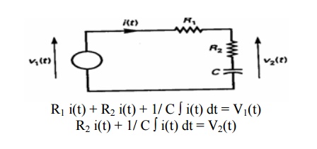
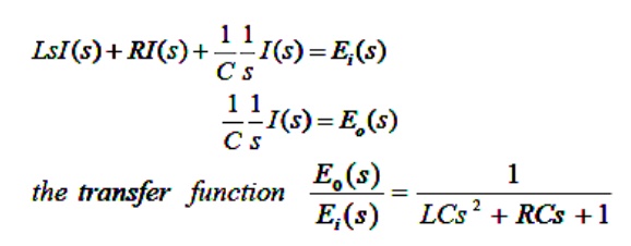
LRC circuit. Applying Kirchhoff‗s voltage law to the system shown. We obtain the following equation;
Resistance circuit
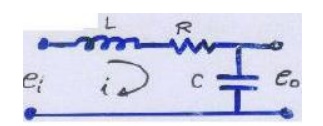
L(di /dt) + Ri + 1/ C ∫ i(t) dt =ei …………………….. (1)
1/ C ∫ i(t) dt =e0 ……………………………………….. (2)
Equation (1) & (2) give a mathematical model of the circuit. Taking the L.T. of equations (1)&(2), assuming zero initial conditions, we obtain
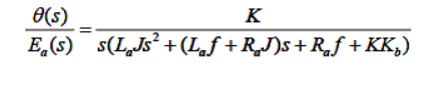
Armature-Controlled dc motors
The dc motors have separately excited fields. They are either armature-controlled with fixed field or field-controlled with fixed armature current. For example, dc motors used in instruments employ a fixed permanent-magnet field, and the controlled signal is applied to the armature terminals.
Consider the armature-controlled dc motor shown in the following figure.
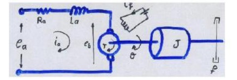
Ra = armature-winding resistance, ohms
La = armature-winding inductance, henrys
ia = armature-winding current, amperes
if = field current, a-pares
ea = applied armature voltage, volt
eb = back emf, volts
θ = angular displacement of the motor shaft, radians
T = torque delivered by the motor, Newton*meter
J = equivalent moment of inertia of the motor and load referred to the motor shaft kg.m2
f = equivalent viscous-friction coefficient of the motor and load referred to the motor shaft. Newton*m/rad/s
T = k1 ia ψ where ψ is the air gap flux, ψ = kf if , k1 is constant
For the constant flux
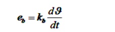
Where Kb is a back emf constant -------------- (1)
The differential equation for the armature circuit
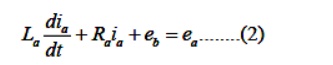
The armature current produces the torque which is applied to the inertia and friction; hence
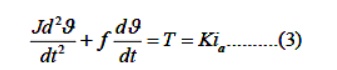
Assuming that all initial conditions are condition are zero/and taking the L.T. of equations (1),
(2) & (3), we obtain
Kps θ (s) = Eb (s)
(Las+Ra ) Ia(s) + Eb (s) = Ea (s) (Js2 +fs)
θ (s) = T(s) = K Ia(s)
The T.F can be obtained is
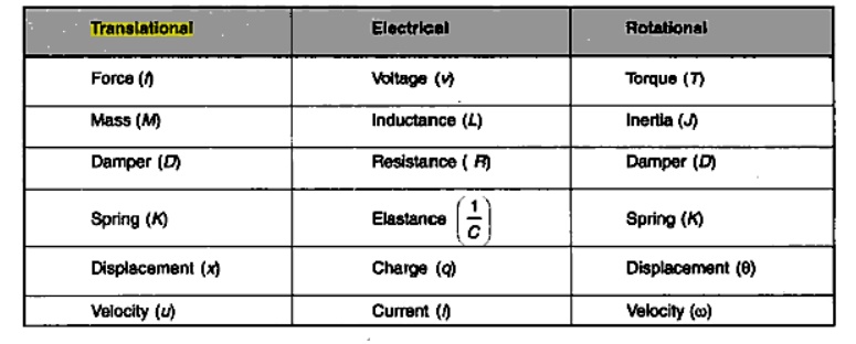
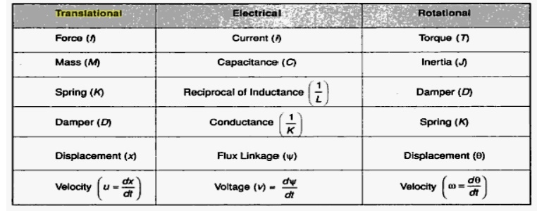
Analogous Systems
Let us consider a mechanical (both translational and rotational) and electrical system as shown in the fig.
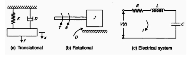
From the fig (a)
We get M d2 x / dt2 + D d x / dt + K x = f
From the fig (b)
We get M d2 θ / dt2 + D d θ / dt + K θ = T
From the fig (c)
We get L d2 q / dt2 + R d q / dt + (1/C) q = V(t)
Where q = ∫i dt
They are two methods to get analogous system. These are (i) force- voltage (f-v) analogy and (ii) force-current (f-c) analogy
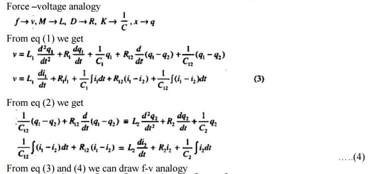
Force –Voltage Analogy
Force – Current Analog
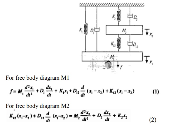
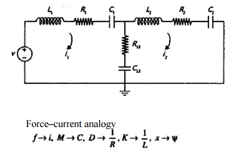
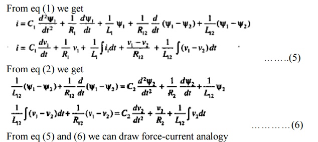
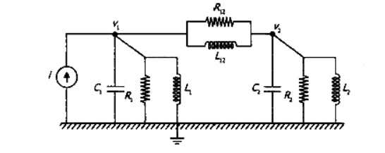
Problem
1. Find the system equation for system shown in the fig. And also determine f-v and f-i analogies
The system can be represented in two forms:
1. Block diagram representation
2. Signal flow graph
Related Topics