Chapter: Design of Electrical Machines : DC Machines
Selection of number of poles
Selection of number of poles
As the armature current increases, cross sectional area of the conductor and hence the eddy current loss in the conductor increases. In order to reduce the eddy current loss in the conductor, cross-sectional area of the conductor must be made less or the current / path must be restricted.
For a normal design, current / parallel path should not be more than about 200A. However, often, under enhanced cooling conditions, a current / path of more than 200A is also being used. By selecting a suitable number of paths for the machine, current / path can be restricted and the number of poles for the machine can be decided. While selecting the number of poles, the following conditions must also be considered as far as possible.
In order to decide what number of poles (more or less) is to be used, let the different factors affecting the choice of number of poles be discussed based on the use of more number of poles.
Frequency
Weight of the iron used for the yoke
Weight of iron used for the armature core (from the core loss point of view)
Weight of overhang copper
Armature reaction
Overall diameter
Length of the commutator
Flash over
Labour charges
Frequency
As the number of poles increases, frequency of the induced EMF f = PN/120 increases core loss in the armature increases and therefore efficiency of the machine decreases.
Weight of the iron used for the yoke
Since the flux carried by the yoke is approximately Žå/2 and the total flux ŽåT = pŽå is a constant for a given machine, flux density in the yoke
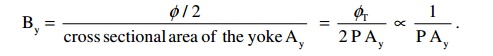
It is clear that Ay is ┬Ą 1/p
as By is also almost constant for a given iron. Thus, as the number of poles increases, Ay and hence the weight of iron used for the yoke reduces.
Weight of iron used for the armature core (from the core loss point of view)
Since the flux carried by the armature core is Žå /2, eddy current loss in the armature core
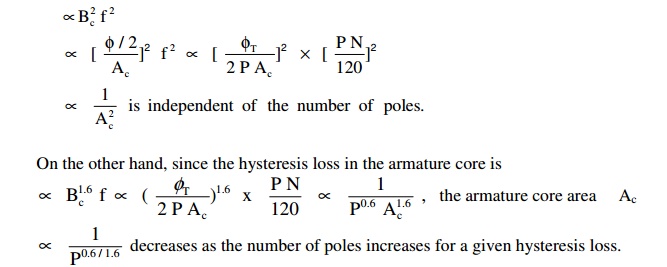
Thus the weight of iron used for the armature core reduces as the number of poles increases.
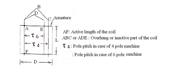
Weight of overhang copper: For a given active length of the coil, overhang ŌłØ pole pitch goes on reducing as the number of poles increases. As the overhang length reduces, the weight of the inactive copper used at the overhang also reduces.
Armature reaction
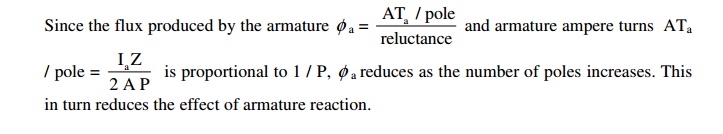
Since the flux produced by the armature and armature ampere turns
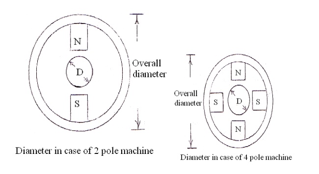
Overall diameter
When the number of poles is less, ATa / pole and hence the flux, produced by the armature is more. This reduces the useful flux in the air gap. In order to maintain a constant value of air gap flux, flux produced by the field or the field ampere-turns must be increased. This calls for more field coil turns and size of the coil defined by the depth of the coil df and height of the coil hf increases. In order that the temperature rise of the coil is not more, depth of the field coil is generally restricted. Therefore height of the field coil increases as the size of the field coil or the number of turns of the coil increases. As the pole height, is proportional to the field coil height, height of the pole and hence the overall diameter of the machine increases with the increase in height of the field coil.
Obviously as the number of poles increases, height of the pole and hence the overall diameter of the machine decreases.
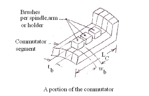
Length of the commutator
Since each brush arm collects the current from every two parallel paths, current / brush arm
= 2 Ia / A and the cross sectional area of the brush / arm
Ab = 2Ia / A╬┤b = 2Ia / P╬┤b
ŌłØ 1 / P
reduces as the number of poles increases.
As Ab = tbwbnb and tb is generally held constant from the commutation point of view, wbnb
reduces as Ab reduces. Hence the length of the commutator
Lc = (wbnb + clearances) reduces as Ab reduces or the number of poles increases.
wb ŌĆō width of the brush,
tb ŌĆō thickness of the brush,
nb ŌĆō number of brushes per spindle
Flash over
As the number of poles increases, voltage between the segments
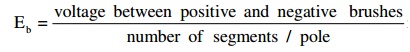
increases. Because of the increased
value of Eb and carbon dust collected in the space where the mica is undercut, chances of arcing between commutator segments increases. The arc between the segments in turn may bridge the positive and negative brushes leading to a dead short circuit of the armature or flash over.
Labour charges
As the number of poles increases cost of labour increases as more number of poles are to be assembled, more field coils are to be wound, placed on to the pole, insulate, interconnect etc.
It is clear that, when the number of poles is more, weight of iron used for yoke and armature core, weight of inactive copper, overall diameter, length of commutator and effect of armature reaction reduces. On the other hand efficiency reduces chances of flash over increases and cost of machine increases.
Since the advantages outnumber the disadvantages, more number of poles is preferable.
Thus, though more number of poles is preferable, it is not advisable from the cost point of view. In general the number of poles should be so selected that good operating characteristics are obtained with minimum weight of active material and minimum cost of construction.
Related Topics