Chapter: Design of Electrical Machines : DC Machines
Design of commutator and brushes
Design of commutator and brushes
The Commutator is an assembly of Commutator segments or bars tapered in section. The segments made of hard drawn copper are insulated from each other by mica or micanite, the usual thickness of which is about 0.8 mm. The number of commutator segments is equal to the number of active armature coils.
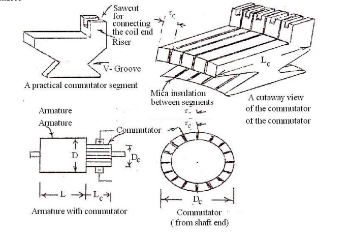
The diameter of the commutator will generally be about (60 to 80)% of the armature diameter. Lesser values are used for high capacity machines and higher values for low capacity machines.
Higher values of commutator peripheral velocity are to be avoided as it leads to lesser commutation time dt, increased reactance voltage and sparking commutation.
The commutator peripheral velocity vc = π DC N / 60 should not as for as possible be more than about 15 m/s. (Peripheral velocity of 30 m/s is also being used in practice but should be avoided whenever possible.)
The commutator segment pitch τC = (outside width of one segment + mica insulation between segments) = π DC / Number of segments should not be less than 4 mm. (This minimum segment pitch is due to 3.2 mm of copper + 0.8 mm of mica insulation between segments.) The outer surface width of commutator segment lies between 4 and 20 mm in practice.
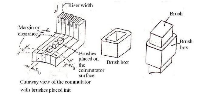
The axial length of the commutator depends on the space required
1) by the brushes with brush boxes
2) for the staggering of brushes
3) for the margin between the end of commutator and brush and
4) for the margin between the brush and riser and width of riser.
If there are nb brushes / brush arm or spindle or holder, placed one beside the other on the commutator surface, then the length of the commutator LC = (width of the brush wb + brush box thickness 0.5 cm) number of brushes / spindle + end clearance 2 to 4 cm + clearance for risers 2 to 4 cm + clearance for staggering of brushes 2 to 4 cm.
If the length of the commutator (as calculated from the above expression) leads to small dissipating surface π DC LC, then the commutator length must be increased so that the temperature rise of the commutator does not exceed a permissible value say 550C.
The temperature rise of the commutator can be calculated by using the following empirical formula.
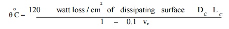
The different losses that are responsible for the temperature rise of the commutator are
a) Brush contact loss and
b) Brush frictional loss.
Brush contact loss = voltage drop / brush set Ă— I
The voltage drop / brush set depend on the brush material – Carbon, graphite, electro graphite or metalized graphite. The voltage drop / brush set can be taken as 2.0 V for carbon brushes. Brush frictional loss (due to all the brush arms)
= frictional torque in Nm Ă— angular velocity
= frictional force in Newton x distance in meter × 2 π N/60
= 9.81 ÎĽPbAball Ă—DC /2Ă—2Ď€ N/60
= 9.81ÎĽPbAball vC
whereÎĽ = coefficient of friction and depends on the brush material. Lies between 0.22 and 0.27 for carbon brushes
Pb = Brush pressure in kg / m2 and lies between 1000 and 1500 Aball = Area of the brushes of all the brush arms in m2
= Ab Ă— number of brush arms
= Ab Ă— number of poles in case of lap winding
= Ab Ă— 2 or P in case of wave winding
Ab = Cross-sectional area of the brush / brush arm
Brush Details
Since the brushes of each brush arm collets the current from two parallel paths, current collected by each brush arm is 2 I/2 Ia and the cross-sectional area of the brush or brush arm or holder or spindle Ab . The current density δp depends on the brush material and can be assumed between 5.5 and 6.5 A / cm2 for carbon.
In order to ensure a continuous supply of power and cost of replacement of damaged or worn out brushes is cheaper, a number of subdivided brushes are used instead of one single brush. Thus if
i) tb is the thickness of the brush
ii) wb is the width of the brush and
iii) nb is the number of sub divided brushes
then Ab = tb wb n
As the number of adjacent coils of the same or different slots that are simultaneously undergoing commutation increases, the brush width and time of commutation also increases at the same rate and therefore the reactance voltage (the basic cause of sparking commutation) becomes independent of brush width.
With only one coil undergoing commutation and width of the brush equal to one segment width, the reactance voltage and hence the sparking increases as the slot width decreases. Hence the brush width is made to cover more than one segment. If the brush is too wide, then those coils which are away from the commutating pole zone or coils not coming under the influence of inter pole flux and undergoing commutation leads to sparking commutation.
Hence brush width greater than the commutating zone width is not advisable under any circumstances. Since the commutating pole zone lies between (9 and 15)% of the pole pitch, 15% of the commutator circumference can be considered as the maximum width of the brush.
It has been found that the brush width should not be more than 5 segments in machines less than
50 kW and 4 segments in machines more than 50 kW.
The number of brushes / spindle can be found out by assuming a standard brush width or a maximum current / sub divided brush.
Standard brush width can be 1.6, 2.2 or 3.2 cm Current/subdivided brush should not be more than 70A
Brush materials and their properties:

Problems:
EX.1. A 500kW, 500V, 375 rpm, 8 pole dc generator has an armature diameter of 110 cm and the number of armature conductor is 896. Calculate the diameter of the commutator, length of the commutator, number of brushes per spindle, commutator losses and temperature rise of the commutator. Assume single turn coils.
Diameter of the commutator DC = (0.6 to 0.8) D = 0.7 x 110 = 77cm Length of the commutator LC = (width of the brush Wb + brush box thickness 0.5 cm) number of brushes / spindle nb + end clearance 2 to 4 cm + clearance for risers 2 to 4 cm + clearance for staggering of brushes 2 to 4 cm.
EX.2. A 600 kW, 6 pole lap connected D.C. generator with commutating poles running at 1200 rpm develops 230V on open circuit and 250V on full load. Find the diameter of the commutator, average volt / conductor, the number of commutator segments, length of commutator and brush contact loss. Take Armature diameter = 56 cm, number of armature conductors = 300, number of slots = 75, brush contact drop = 2.3 V, number of carbon brushes = 8 each 3.2 cm x 2.5 cm. The voltage between commutator segments should not exceed 15V.
Related Topics