Chapter: Design of Electrical Machines : DC Machines
Design of Armature
Design of Armature
The armature winding can broadly be classified as concentrated and distributed winding.
In case of a concentrated winding, all the conductors / pole is housed in one slot. Since the conductors / slot is more, quantity of insulation in the slot is more, heat dissipation is less, temperature rise is more and the efficiency of operation will be less. Also emf induced in the armature conductors will not be sinusoidal. Therefore
a. design calculations become complicated (because of the complicated expression of non-sinusoidal wave).
b. Core loss increases (because of the fundamental and harmonic components of the non-sinusoidal wave) and efficiency reduces.
c. Communication interference may occur (because of the higher frequency components of the non-sinusoidal wave).
Hence no concentrated winding is used in practice for a DC machine armature.
In a distributed winding (used to overcome the disadvantages of the concentrated winding), conductors / pole is distributed in more number of slots. The distributed winding can be classified as single layer winding and double layer winding.
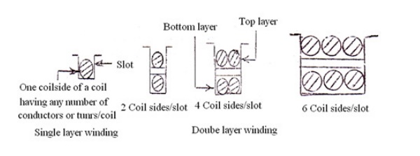
In a single layer winding, there will be only one coil side in the slot having any number of conductors, odd or even integer depending on the number of turns of the coil. In a double layer winding, there will be 2 or multiple of 2 coil sides in the slot arranged in two layers. Obviously conductors / slot in a double layer winding must be an even integer.
Since for a given number of conductors, poles and slots, a single layer winding calls for less number of coils of more number of turns, reactance voltage proportional to (turn)2 is high. This decreases the quality of commutation or leads to sparking commutation. Hence a single layer winding is not generally used in DC machines. However it is much used in alternators and induction motors where there is no commutation involved.
Since a double layer winding calls for more number of coils of less number of turns/coil, reactance voltage proportional to (turn)2 is less and the quality of commutation is good. Hence double layer windings are much used in DC machines.
Unless otherwise specified all DC machines are assumed to be having a double layer winding.
A double layer winding can further be classified as simplex or multiplex and lap or wave winding. In order to decide what number of slots (more or less) is to be used, the following merits and demerits are considered.
NUMBER OF ARMATURE SLOTS
1. As the number of slots increases, cost of punching the slot increases, number of coils increases and hence the cost of the machine increases.
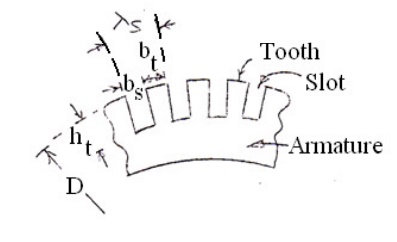
2. As the number of slots increases, slot pitch
╬╗s = (slot width bs + tooth width bt)
= ŽĆD/ number of slots S
decreases and hence the tooth width reduces. This makes the tooth mechanically weak, increases the flux density in the tooth and the core loss in the tooth. Therefore efficiency of the machine decreases.
If the slots are less in number, then the cost of punching & number of coils decreases, slot pitch increases, tooth becomes mechanically strong and efficiency increases, quantity of insulation in the slot increases, heat dissipation reduces, temperature increases and hence the efficiency decreases.
It is clear that not much advantage is gained by the use of either too a less or more number of slots. As a preliminary value, the number of slots can be selected by considering the slot pitch. The slot pitch can assumed to be between (2.5 and 3.5) cm. (This range is applicable to only to medium capacity machines and it can be more or less for other capacity machines).
The selection of the number of slots must also be based on the type of winding used, quality of commutation, flux pulsation etc.
When the number of slot per pole is a whole number, the number slots embraced by each pole will be the same for all positions of armature. However, the number teeth per pole will not be same.
This causes a variation in reluctance of the air gap and the flux in the air gap will pulsate. Pulsations of the flux in the air gap produce iron losses in the pole shoe and give rise to magnetic noises. On the other hand, when the slots per pole is equal to a whole number plus half the reluctance of the flux path per pole pair remains constant for all positions of the armature, and there will be no pulsations or oscillations of the flux in the air gap.
To avoid pulsations and oscillations of the flux in the air gap, the number of slots per pole should be a whole number plus half. When this is not possible or advisable for other reasons, the number of slots per pole arc should an integer.
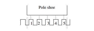
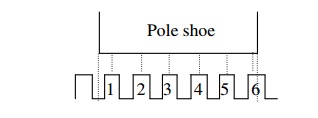
Number of teeth/pole shoe = 5 and flux passes through 5 teeth.
The reluctance of the air gap is inversely proportional to the area corresponding to 5 teeth.
Number of teeth/pole shoe = 5 and flux passes through 6 teeth when the armature is moved half tooth pitch to the right.The reluctance of the air gap is inversely proportional to the area corresponding to 6 teeth. The reluctance in this case is less and the flux is more compared to the former case. Therefore, the flux pulsates i.e. Varies in magnitude.
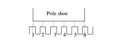
Number of teeth/pole shoe = (5+ 0.5) and flux passes through 6 teeth. The reluctance of the air gap is inversely proportional to the area corresponding to 6 teeth.
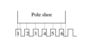
Number of teeth/pole shoe = (5+0.5) and flux passes through 6 teeth when the armature is moved half tooth pitch to the right.The reluctance of the air gap is inversely proportional 6 teeth as before. The reluctance and the flux in both the cases remains the same in all positions of the armature. However, the reluctance and the flux under the tips of the pole are not the same for all the positions of armature. Therefore when the armature rotates the flux under the pole oscillates between the pole tips. This produces ripple in the voltage induced in the conductors moving under poles.
The flux pulsation under inter pole causes the sparking. A small tooth pitch helps to reduce the effect of armature slots upon the inter poles.
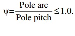
To obtain good commutation, the flux density in the air gap must decrease gradually from maximum value under the center of the pole to zero on the center line between two poles, and the flux densities near the neutral point must be low. A field form that drops off rapidly from maximum value to zero not only leads to commutation difficulties but may also give rise to noises in machines with slotted armatures. In order to achieve good commutation the pole shoe is designed to cover only certain percentage of the pole pitch. The circumferential distance covered by the pole shoe on the armature surface is called the pole arc. The ratio of the pole arc to pole pitch is called per unit embrace or enclosure. That is, per unit enclosure
In practice Žł lies between 0.6 and 0.7.
Related Topics