Chapter: Television and Video Engineering : Advanced Television Systems
Satellite TV
Satellite TV
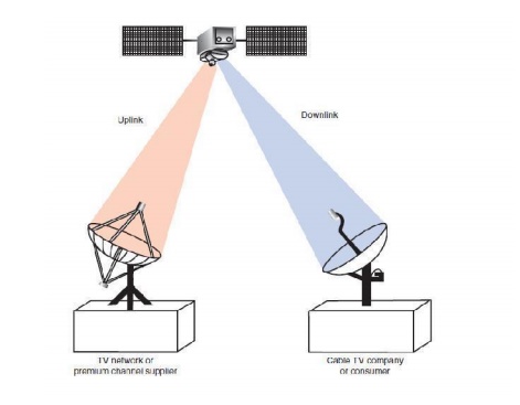
One of the most common methods of TV signal distribution is via communication satellite.A communication satellite orbits the equator about 22,300 mi out in space. It rotates in synchronism with the earth and therefore appears to be stationary. The satellite is used as a radio relay station.
The TV signal to be distributed is used to modulate a microwave carrier, and then it is transmitted to the satellite. The path from earth to the satellite is called the uplink. The satellite translates the signal to another frequency and then retransmits it back to earth. This is called the downlink. A receive site on earth picks up the signal.
The receive site may be a cable TV company or an individual consumer. Satellites are widely used by the TV networks, the premium channel companies, and the cable TV industry for distributing signals nationally.
A newer form of consumer satellite TV is direct broadcast satellite (DBS) TV. The DBS systems are designed specifically for consumer reception directly from the satellite. The new DBS systems feature digitally encoded video and audio signals, which make transmission and reception more reliable and provide outstanding picture and sound quality.
By using higher-frequency microwaves, higher-power satellite transponders, and very low-noise GaAs FETs in the receiver, the customer’s satellite dish can be made very small. These systems typically use an 18-in dish as opposed to the 5- to 12-ft-diameter dishes still used in older satellite TV systems.
Direct Broadcast Satellite Systems
The direct broadcast satellite (DBS ) system was designed specifically to be an all-digital system. Data compression techniques are used to reduce the data rate required to produce high-quality picture and sound.
The DBS system features entirely digital uplink ground stations and satellites. Since the satellites are designed to transmit directly to the home, extra high-power transponders are used to ensure a satisfactory signal level.
To receive the digital video from the satellite, a consumer must purchase a satellite TV receiver and antenna.
These satellite receivers operate in the band. By using higher frequencies as well as higher-power satellite transponders, the necessary dish antenna can be extremely small. The new satellite DBS system antennas have only an 18-in diameter.
Several special digital broadcast satellites are in orbit, and two of the direct satellite TV sources are DirecTV and DISH Network. They provide full coverage of the major cable networks, and the premium channels usually distributed to homes by cable TV and can be received directly.
In addition to purchasing the receiver and antenna, the consumer must subscribe to one of the services supplying the desired channels. Satellite Transmission. The video to be transmitted must first be placed into digital form. To digitize an analog signal, it must be sampled a minimum of 2 times per cycle for sufficient digital data to be developed for reconstruction of the signal.
Assuming that video frequencies of up to 4.2 Mbps are used, the minimum sampling rate is twice this, or 8.4 Mbps. For each sample, a binary number proportional to the light amplitude is developed. This is done by an A/D converter, usually with an 8-bit output. The resulting video signal, therefore, has a data rate of 8 bits, 8.4 Mbps, or 67.2 Mbps. This is an extremely high data rate.
However, for a color TV signal to be transmitted in this way, there must be a separate signal for each of the red, green, and blue components making up the video. This translates to a total data rate of or 202, Mbps. Even with today’s technology, this is an extremely high data rate that is hard to achieve reliably.
To lower the data rate and improve the reliability of transmission, the new DBS system uses compressed digital video. Once the video signals have been put into digital form, they are processed by digital signal processing (DSP) circuits to minimize the full amount of data to be transmitted.
Digital compression greatly reduces the actual transmitting speed to somewhere in the 20-to 30-Mbps range. The compressed serial digital signal is then used to modulate the uplinked carrier using BPSK.
The DBS satellite uses the band with a frequency range of 11 to 14 GHz. Uplink signals are usually in the 14- to 14.5-GHz range, and the downlink usually covers the range of 10.95 to 12.75 GHz. The primary advantage of using the band is that the receiving antennas may be made much smaller for a given amount of gain.
However, these higher frequencies are more affected by atmospheric conditions than are the lower microwave frequencies. The biggest problem is the increased attenuation of the downlink signal caused by rain.
Any t ype of weather involving rain or water vapor, such as fog, can seriously reduce the received signal. This is so because the wavelength of band signals is near that of water vapor. Therefore, the water vapor absorbs the signal.
Although the power of the satellite transponder and the gain of the receiving antenna are typically sufficient to provide solid reception, there can be fadeout under heavy downpour conditions.
Finally, the digital signal is transmitted from the satellite to the receiver by using circular polarization. The DBS satellites have right-hand and left-hand circularly polarized (RHCP and LHCP) helical antennas.
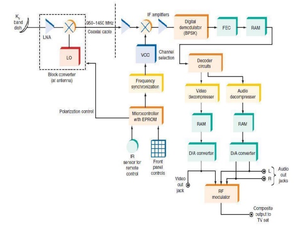
By transmitting both polarities of signal, frequency reuse can be incorporated to double the channel capacity. DBS Receiver. A block diagram of a typical DBS digital receiver is shown in Fig. The receiver subsystem begins with the antenna and its low-noise block converter.
The horn antenna picks up the band signal and translates the entire 500-MHz band used by the signal down to the 950- to 1450-MHz range, as explained earlier. Control signals from the receiver to the antenna select between RHCP and LHCP. The RF signal from the antenna is sent by coaxial cable to the receiver.
A typical DBS downlink signal occurs in the 12.2- to 12.7-GHz portion of the band. Each
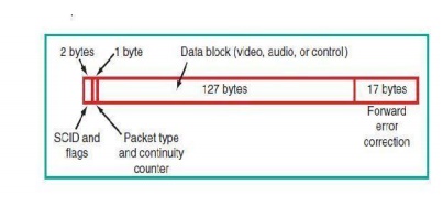
transponder has a bandwidth of pproximately 24 MHz. The digital signal usually occurs at a rate of approximately 27 Mbps. Figure shows how the digital signal is transmitted. The digital audio and video signals are organized into data packets.
Each packet consists of a total of 147 bytes. The first 2 bytes (16 bits) contain the service channel identification (SCID) number. This is a 12-bit number that identifies the video program being carried by the packet. The 4 additional bits are used to indicate whether the packet is encrypted and, if so, which decoding key to use.
One additional byte contains the packet type and a continuity counter. The data block consists of 127 bytes, either 8-bit video signals or 16-bit audio signals. It may also contain digital data used for control purposes in the receiver.
Finally, the last 17 bytes are the error detection check codes. These 17 bytes are developed by an error-checking circuit at the transmitter. The appended bytes are checked at the receiver to detect any errors and correct them.
Digital data packet format used in DBS TV.
The received signal is passed through another mixer with a variable-frequency local oscillator to provide channel selection. The digital signal at the second IF is then demodulated to recover the originally transmitted digital signal, which is passed through a forward error correction (FEC) circuit.
This circuit is designed to detect bit errors in the transmission and to correct them on the fly. Any bits lost or obscured by noise during the transmission process are usually caught and corrected to ensure a near-perfect digital signal.
The resulting error-corrected signals are then sent to the audio and video decompression circuits. Then they are stored in random access memory (RAM), after which the signal is decoded to separate it into both the video and the audio portions.
The DBS TV system uses digital compression-decompression standards referred to as
MPEG2 (MPEG means Moving Picture Experts Group, which is a standards organization that establishes technical standards for movies and video).
MPEG2 is a compression method for video that achieves a compression of about 50 to 1 in data rate. Finally, the signals are sent to D/A converters that modulate the RF modulator which sends the signals to the TV set antenna terminals.
Although the new DBS digital systems will not replace cable TV, they provide the consumer with the capability of receiving a wide range of TV channels. The use of digital techniques provides an unusually high-quality signal.
Related Topics