Chapter: Television and Video Engineering : Advanced Television Systems
Cable Television
CABLE TELEVISION
In recent year’s master antenna (MATV) and community antenna (CATV) television systems have gained widespread popularity. The purpose of a MATV system is to deliver a strong signal (over 1 mV) from one or more antennas to every television receiver connected to the system.
Typical applications of a MATV system are hotels, motels, schools, apartment buildings and so on. The CATV system is a cable system which distributes good quality television signal to a very large number of receivers throughout an entire community.
In general, this system feeds increased TV programmes to subscribers who pay a fee for this service. A CATV system may have many more active (VHF and UHF) channels than a receiver tuner can directly select. This requires use of a special active converter in the head-end.
(a) MATV
The block diagram of a basic MATV system is shown in Fig. One or more antennas are usually located on roof top, the number depending on a available telecasts and their direction.
Each antenna is properly oriented so that all stations are received simultaneously. In order to allow a convenient match between the coaxial transmission line and components that make up the system, MATV systems are designed to have a 75 Ω impedance. Since most antennas have a 300 Ω impedance, a balun is used to convert the impedance to 75 ohms.
As shown in the figure, antenna outputs feed into a 4-way hybrid. A hybrid is basically a signal combining linear mixer which provides suitable impedance matches to prevent development of standing waves.
The standing waves, if present, result in ghosts appearing in an otherwise good TV picture. The output from the hybrid feeds into a distribution amplifier via a preamplifier. The function of these amplifiers is to raise the signal amplitude to a level which is sufficient to overcome the losses of the distribution system while providing an acceptable signal to every receiver in the system.
The output from the distribution amplifier is fed to splitters through coaxial trunk lines. A splitter is a resistive-inductive device which provides trunk line isolation and impedance match. Coaxial distribution lines carry television signals from the output of splitters to points of delivery called subscriber tap-offs.
The subscriber taps, as shown in Fig, can be either transformer coupled, capacitive coupled or in the form of resistive pads. They provide isolation between receivers on the same line thus preventing mutual interference. The taps look like ac outlets and are normally mounted in the wall.
Wall taps may be obtained with 300 Ω output 75 Ω output and a dual output. The preferred method is to use a 75 Ω type with a matching transformer. The matching transformer is usually mounted at the antenna terminals of the receiver and will have a VHF output and a UHF output.
Since improperly terminated lines will develop standing waves, the end of each 75 Ω distribution cable is terminated with a 75 Ω resistor called a terminator.
(b) CATV
Formerl y CATV system were employed only in far-fringe areas or in valleys surrounded by mountains where reception was difficult or impossible because of low level signal conditions.
However, CATV systems are now being used in big cities where signal-level is high but all buildings render signals weak and cause ghosts due to multipath reflections. In either case, such a system often serves an entire town or city.
A single antenna site, which may be on top of a hill, mountain or sky-scraper is chosen for fixing antennas. Several high gain and properl y oriented antennas are employed to pick up signals from different stations. In areas where several signals are coming from one direction, a single broad based antenna (log-periodic) may be used to cover those channels.
Most cable television installations provide additional services like household, business and educational besides commercial TV and FM broadcast programmes. These include news, local sports and community programmes, burglar and fire alarms, weather reports, commercial data retrieval, meter reading, document reproduction etc.
Educational services include computer aided instructions, centralized library services and so on. Many of the above options require extra subscription fee from the subscriber.
Since several of the above mentioned service need two-way communication between the subscriber and a central processor, the coaxial distribution network has a large number of cable pairs, usually 12 or 24.
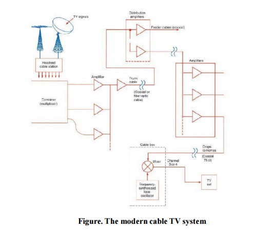
This enables the viewer to choose any channel or programme out of the many that are available at a given time. CATV Plan. Figure 10.2 shows the plan of a typical CATV system. The signals from various TV channels are processed in the same manner as in a MATV system. In fact, a CATV system can be combined with a MATV set-up.
When UHF reception is provided in addition to VHF, as often is the case, the signal from each UHF channel is processed by a translator. A translator is a frequency converter which hterodynes the UHF channel frequencies down to a VHF channel.
Translation is advantageous since a CATV system necessarily operates with lengthy coaxial cables and the transmission loss through the cable is much greater at UHF than at VHF frequencies. As in the case of MATV, various inputs including those from translators are combined in a suitable mixer.
The set-up from the antennas to this combiner is called a head-end. Further, as shown in the figure the CATV outputs from the combiner network are fed to a number of trunk cables through a broadband distribution amplifier. The trunk cables carry signals from the antenna site to the utilization site (s) which may be several kilometers away. Feeder amplifiers are provided at several points along the line to overcome progressive signal attenuation which occurs due to cable losses.
Since cable losses are greater at higher frequencies it is evident that high-band attenuation will be greater than low-band attenuation. Therefore, to equalize this the amplifiers and signal splitters are often supplemented by equalizers. An equalizer or tilt control consists of a band pass filter arrangement with an adjustable frequency response. It operates by introducing a relative low-frequency loss so that outputs from the amplifiers or splitters have uniform relative amplitude response across the entire VHF band.
The signal distribution from splitters to tap-off points is done through multicore coaxial cables in the same way as in a MATV system. In any case the signal level provided to a television receiver is of the order of 1.5 mV.
This level provides good quality reception without causing accompanying radiation problems from the CATV system, which could cause interference to other installations and services.
Signal Processing
The TV signals to be redistributed by the cable company usually undergo some kind of processing before they are put on the cable to the TV set. Amplification and impedance matching are the main processes involved in sending the signal to remote locations over what is sometimes many miles of coaxial cable. However, at the head end, other types of processes are involved.(Coaxial or fiber-optic cable)Frequency synthesized local oscillator
Straight-Through Processors.
In early cable systems, the TV signals from local stations were picked up with antennas, and the signal was amplified before being multiplexed onto the main cable. This is called straight-through processing. Amplifiers called strip amplifiers and tuned to the received channels pass the desired TV signal to the combiner.
Most of these amplifiers include some kind of gain control or attenuators that can reduce the signal level to prevent distortion of strong local signals. This process can still be used with local VHF TV stations, but today heterodyne processing is used instead.
Heterodyne Processors.
Heterodyne processing translates the incoming TV signal to a different frequency. This is necessary when satellite signals are involved.
Microwave carriers cannot be put on the cable, so they are down-converted to some available 6-MHz TV channel.
In addition, heterodyne processing gives the cable companies the flexibility of putting the signals on any channel they want to use.
The cable TV industry has created a special set of non-broadcast TV channels, some of the frequency assignments correspond to standard TV channels, but others do not. Since all these frequencies are confined to a cable, there can be duplication of any frequency that might be used in radio or TV broadcasting.
Note that the spacing between the channels is 6 MHz.
Related Topics