Chapter: Television and Video Engineering : Advanced Television Systems
HDTV Transmission Concepts: Transmitter, Receiver
HDTV Transmission Concepts
In HDTV both the video and the audio signals must be digitized by A/D converters and transmitted serially to the receiver.
Because of the very high frequency of video signals, special techniques must be used to transmit the video signal over a standard 6-MHz-bandwidth TV channel.
And because both video and audio must be transmitted over the same channel, multiplexing techniques must be used. The FCC’s requirement is that all this information be transmitted reliably over the standard 6-MHz TV channels now defined for NTSC TV. Assume that the video to be transmitted contains frequencies up to 4.2 MHz.
For this signal to be digitized, it must be sampled at least 2 times per cycle or at a minimum sampling rate of 8.4 MHz. If each sample is translated to an 8-bit word (byte) and the bytes are transmitted serially, the data stream has a rate of , or 67.2 MHz.
Multiply this by 3 to get 67.2 _ 3 = 201.6 MHz. Add to this the audio channels, and the total required bandwidth is almost 300 MHz. To permit this quantity of data to be transmitted over the 6-MHz channel, special encoding and modulation techniques are used.
HDTV Transmitter
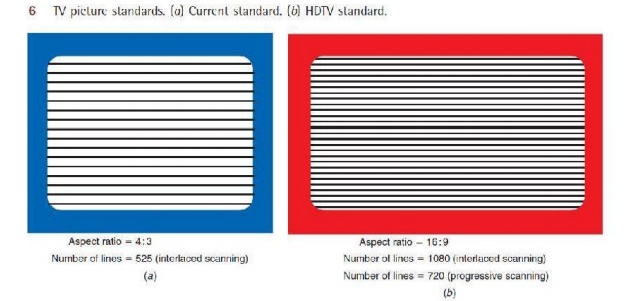
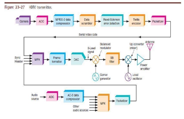
Figure shows a block diagram of an HDTV transmitter. The video from the camera consists of the R, G, and B signals that are converted to the luminance and chrominance signals. These are digitized by A/D converters. The luminance sampling rate is 14.3 MHz, and the chroma sampling rate is 7.15 MHz.
The resulting signals are serialized and sent to a data compressor. The purpose of this device is to reduce the number of bits needed to represent the video data and therefore permit higher transmission rates in a limited-bandwidth channel. MPEG-2 is the data compression method used in HDTV.
The MPEG-2 data compressor processes the data according to an algorithm that effectively reduces any redundancy in the video signal. For example, if the picture is one-half light blue sky, the pixel values will be the same for many lines.
All this data can be reduced to one pixel value transmitted for a known number of times. The algorithm also uses fewer bits to encode the color than to encode the brightness because the human eye is much more sensitive to brightness than to color.
The MPEG-2 encoder captures and compares successive frames of video and compares them to detect the redundancy so that only differences between successive frames are transmitted. The signal is next sent to a data randomizer. The randomizer scrambles or randomizes the signal.
This is done to ensure that random data is transmitted even when no video is present or when the video is a constant value for many scan lines. This permits clock recovery at the receiver.
Next the random serial signal is passed through a Reed-Solomon (RS) error detection and correction circuit. This circuit adds extra bits to the data stream so that transmission errors can be detected at the receiver and corrected. This ensures high reliability in signal transmission even under severe noise conditions.
In HDTV, the RS encoder adds 20 parity bytes per block of data that can provide correction for up to 10 byte errors per block. The signal is next fed to a trellis encoder. This circuit further modifies the data to permit error correction at the receiver. Trellis encoding is widely used in modems.
Trellis coding is not used in the cable TV version of HDTV. The audio portion of the HDTV signal is also digital. It provides for compact disk (CD) quality audio. The audio system can accommodate up to six audio channels, permitting monophonic sound, stereo, and multichannel surround sound.
The channel arrangement is flexible to permit different systems. For example, one channel could be used for a second language transmission or closed captioning. Each audio channel is sampled at a 48-kbps rate, ensuring that audio signals up to about 24 kHz are accurately captured and transmitted.
Each audio sample is converted to an 18-bit digital word. The audio information is time-multiplexed and transmitted as a serial bit stream at a frequency of A data compression technique designated AC-3 is used to speed up audio transmission.
Next the video and audio data streams are packetized; i.e., they are converted to short blocks of data bytes that segment the video and audio signals.
These packets are multiplexed along with some synchronizing signals to form the final signal to be transmitted. The result is a 188-bit packet containing both video and audio data plus 4 bytes of synchronizing bytes and a header. See Fig.
The header identifies the number of the packet and its sequence as well as the video format. Next the packets are assembled into frames of data representing one frame of video. The complete frame consists of 626 packets transmitted sequentially. The final signal is sent to the modulator.
The modulation scheme used in HDTV is 8-VSB, or eight-level vestigial sideband, amplitude modulation. The carrier is suppressed, and only the upper sideband is transmitted.
The serial digital data is sent to a D/A converter where each sequential 3-bit group is converted to a discrete voltage level. This system encodes 3 bits per symbol, thereby greatly increasing the data rate within the channel. An example is shown in Fig. Each 3-bit group is converted to a relative level of or This is the signal that amplitude-modulates the carrier.
he resulting symbol rate is 10,800 symbols per second. This translates to a data rate of . Eliminating the extra RS and trellis bits gives an actual video/audio rate of about 19.3 Mbps. A modified version of this format is used when the HDTV signal is to be transmitted over a cable system. Trellis coding is eliminated and 16-VSB modulation is used to encode 4 bits per symbol.
This gives double the data rate of terrestrial HDTV transmission (38.6 Mbps). The VSB signal can be created with a balanced modulator to eliminate the carrier and to generate the sidebands.
One sideband is removed by a filter or by using the phasing system. The modulated signal is up-converted by a mixer to the final transmission frequency, which is one of the standard TV channels in the VHF or UHF range. A linear power amplifier is used to boost the signal level prior to transmission by the antenna.
HDTV Receiver.
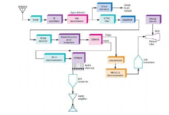
An HDTV receiver picks up the composite signal and then demodulates and decodes the signal into the original video and audio information. A simplified receiver block diagram is shown in Fig.
The tuner and IF systems are similar to those in a standard TV receiver. From there the 8-VSB signal is demodulated (using asynchronous detector) into the original bit stream. A balanced modulator is used along with a carrier signal that is phase-locked to the pilot carrier to ensure accurate demodulation.
A clock recovery circuit regenerates the clock signal that times all the remaining digital operations. The signal then passes through an NTSC filter that is designed to filter out any one channel or adjacent channel interference from standard TV stations.
The signal is also passed through an equalizer circuit that adjusts the signal to correct for amplitude and phase variations encountered during transmission. The signals are de-multiplexed into the video and audio bit streams.
Next, the trellis decoder and RS decoder ensure that any received errors caused by noise are corrected. The signal is descrambled and decompressed. The video signal is then converted back to the digital signals that will drive the D/A converters that, in turn, drive the red, green, and blue electron guns in the CRT.
The audio signal is also de multiplexed and fed to AC-3 decoders. The resulting digital signals are fed to D/A converters that create the analog audio for each of the six audio channels.
Related Topics