Chapter: Compilers : Principles, Techniques, & Tools : Code Generation
Register Allocation and Assignment
Register Allocation and
Assignment
1 Global Register Allocation
2 Usage Counts
3 Register Assignment for Outer
Loops
4 Register Allocation by Graph
Coloring
5 Exercises for Section 8.8
Instructions involving only register operands are
faster than those involving memory operands. On modern machines, processor
speeds are often an order of magnitude or more faster than memory speeds.
Therefore, efficient utilization of registers is vitally important in
generating good code. This section presents various strategies for deciding at
each point in a program what values should reside in registers (register
allocation) and in which register each value should reside (register
assignment).
One approach to register allocation
and assignment is to assign specific values in the target program to certain
registers. For example, we could decide to assign base addresses to one group
of registers, arithmetic computations to another, the top of the stack to a
fixed register, and so on.
This approach has the advantage
that it simplifies the design of a code gener-ator. Its disadvantage is that,
applied too strictly, it uses registers inefficiently; certain registers may go
unused over substantial portions of code, while unnec-essary loads and stores
are generated into the other registers. Nevertheless, it is reasonable in most
computing environments to reserve a few registers for base
registers, stack pointers, and the like, and to
allow the remaining registers to
be used by the code generator as it sees fit.
1. Global Register Allocation
The code generation algorithm in Section 8.6 used registers to hold
values for the duration of a single basic block. However, all live variables
were stored at the end of each block. To save some of these stores and
corresponding loads, we might arrange to assign registers to frequently used
variables and keep these registers consistent across block boundaries (globally). Since programs spend most of
their time in inner loops, a natural approach to global register assignment is
to try to keep a frequently used value in a fixed register throughout a loop.
For the time being, assume that we know the loop structure of a flow graph, and
that we know what values computed in a basic block are used outside that block.
The next chapter covers techniques for computing this information.
One strategy for global register
allocation is to assign some fixed number of registers to hold the most active
values in each inner loop. The selected values may be different in different
loops. Registers not already allocated may be used to hold values local to one
block as in Section 8.6. This approach has the drawback that the fixed number
of registers is not always the right number to make available for global
register allocation. Yet the method is simple to implement and was used in
Fortran H, the optimizing Fortran compiler developed by IBM for the 360-series
machines in the late 1960s.
With early C compilers, a
programmer could do some register allocation explicitly by using register
declarations to keep certain values in registers for the duration of a
procedure. Judicious use of register declarations did speed up many programs,
but programmers were encouraged to first profile their programs to determine
the program's hotspots before doing their own register allocation.
2. Usage Counts
In this section we shall assume that the savings to be realized by
keeping a variable x in a register
for the duration of a loop L is one
unit of cost for each reference to x
if x is already in a register.
However, if we use the approach in Section 8.6 to generate code for a block,
there is a good chance that after x
has been computed in a block it will remain in a register if there are
subsequent uses of x in that block.
Thus we count a savings of one for each use of x in loop L that is not
preceded by an assignment to x in the
same block. We also save two units if we can avoid a store of x at the end of a block. Thus, if x is allocated a register, we count a
savings of two for each block in loop L
for which x is live on exit and in
which x is assigned a value.
On the debit side, if x is
live on entry to the loop header, we must load x into its register just before entering loop L. This load costs two units. Similarly, for each exit block B of loop L at which x is live on
entry to some successor of B outside
of L, we must store x at a cost of
two. However, on the assumption that
the loop is iterated many times, we may neglect these debits since they occur
only once each time we enter the loop. Thus, an approximate formula for the
benefit to be realized from allocating a register x within loop L is
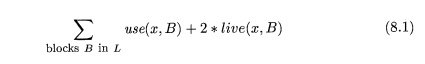
where use(x, B) is the number of times x is used in B prior to any
definition of x; live(x, B) is 1 if x is live on exit from B and is
assigned a value in B, and live(x, B) is 0 otherwise. Note that (8.1) is approximate, because not
all blocks in a loop are executed with equal frequency and also because (8.1)
is based on the assumption that a loop is iterated many times. On specific
machines a formula analogous to (8.1), but possibly quite different from it,
would have to be developed.
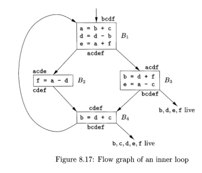
Example 8 . 1 7 : Consider the
the basic blocks in the inner loop depicted in Fig. 8.17, where
jump and conditional jump statements have been omitted. Assume registers RO, Rl, and R2 are
allocated to hold values throughout the loop. Variables live on entry into and
on exit from each block are shown in Fig. 8.17 for
convenience, immediately above and below each block, respectively. There are
some subtle points about live variables that we address in the next chapter.
For example, notice that both e and f are live at the end of B1, but of these, only e is live on
entry to B2 and only f on entry to B3. In general, the variables live at the end of a block are the union of
those live at the beginning of each of its successor blocks.
To evaluate (8.1) for x = a, we
observe that a is live on exit from Bi and
is assigned a value there, but is not live on exit from B2, B3, or B4. Thus, J2B in L use(a.:B) — 2. Hence the value of (8.1) for x — a is 4. That is, four units of cost can be saved by selecting a for one
of the global registers. The values of (8.1) for b, c, d, e,
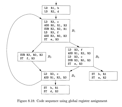
and f are 5, 3, 6, 4, and 4, respectively. Thus, we may select a, b, and d
for registers RO,
Rl, and R2,
respectively. Using RO for e or f instead of a would be another choice with the same apparent benefit. Figure 8.18 shows
the assembly code generated from Fig. 8.17, assuming
that the strategy of Section 8.6 is used to generate code for each block. We do not show the generated
code for the omitted conditional or unconditional jumps that end each block in
Fig. 8.17, and we therefore do not show the generated code as a single stream as
it would appear in practice.
3. Register Assignment for Outer
Loops
Having assigned registers and generated code for
inner loops, we may apply the same idea to progressively larger enclosing
loops. If an outer loop L1 contains
an inner loop L2, the names allocated registers in L2 need not be allocated registers in L1 — L2. Similarly, if we choose to allocate x a
register in L2 but not Li, we must
load x on entrance to L2 and store x
on exit from L2. We leave as an exercise the derivation of a criterion for
selecting names to be allocated registers in an outer loop L, given that
choices have already been made for all loops nested within L.
4. Register Allocation by Graph
Coloring
When a register is needed for a computation but all available registers
are in use, the contents of one of the used registers must be stored (spilled) into a memory location in
order to free up a register. Graph coloring is a simple, systematic technique
for allocating registers and managing register spills.
In the method, two passes are used. In the
first, target-machine instructions are
selected as though there are an infinite number of symbolic registers; in
effect, names used in the intermediate code become names of registers and the
three-address instructions become machine-language instructions. If ac-cess to
variables requires instructions that use stack pointers, display pointers, base
registers, or other quantities that assist access, then we assume that these
quantities are held in registers reserved for each purpose. Normally, their use
is directly translatable into an access mode for an address mentioned in a
machine instruction. If access is more complex, the access must be broken into
several machine instructions, and a temporary symbolic register (or several)
may need to be created.
Once the instructions have been
selected, a second pass assigns physical registers to symbolic ones. The goal
is to find an assignment that minimizes the cost of spills.
In the second pass, for each
procedure a register-interference graph
is con-structed in which the nodes are symbolic registers and an edge connects
two nodes if one is live at a point where the other is defined. For example, a
register-interference graph for Fig. 8.17 would have nodes for names a and d.
In block By, a is live at the second
statement, which defines d; therefore, in the graph there would be an edge between the nodes for a and d.
An attempt is made to color the
register-interference graph using k
colors, where k is the number of
assignable registers. A graph is said to be colored
if each node has been assigned a color in such a way that no two adjacent nodes
have the same color. A color represents a register, and the color makes sure
that no two symbolic registers that can interfere with each other are assigned
the same physical register.
Although the problem of
determining whether a graph is fc-colorable is NP - complete in general, the
following heuristic technique can usually be used to do the coloring quickly in
practice. Suppose a node n in a graph
G has fewer than k neighbors (nodes connected to
n by an edge). Remove n and its
edges from G to obtain a graph G'. A ^-coloring of G' can be extended to a fc-coloring of G by assigning n a color not assigned to any of its neighbors.
By repeatedly eliminating nodes
having fewer than k edges from the
register-interference graph, either we obtain the empty graph, in which case we
can produce a ^-coloring for the original graph by coloring the nodes in the
reverse order in which they were removed, or we obtain a graph in which each
node has k or more adjacent nodes. In
the latter case a ^-coloring is no longer possible. At this point a node is spilled by introducing code to store and
reload the register. Chaitin has devised several heuristics for choosing the
node to spill. A general rule is to avoid introducing spill code into inner
loops.
5. Exercises
for Section 8.8
Exercise 8.8. 1 : Construct the
register-interference graph for the
program in Fig. 8.17.
Exercise 8.8. 2: Devise a
register-allocation strategy on the assumption
that we automatically store all registers on the stack before each procedure
call and restore them after the return.
Related Topics