Chapter: Civil : Principles of Solid Mechanics : Linear Free Fields
Pure Bending of Prismatic Bars
Pure Bending of
Prismatic Bars
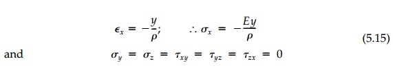
Elementary beam theory, where axial strains and therefore stresses are pro-portional to the bending moment and vary linearly from a centroidal axis, is an exact solution for pure bending of a prismatic bar if body forces are neglected. Consider a beam such as that shown in Figure 5.6 with the y, z coordinates at the centroid of the rectangular cross-section oriented with the principal directions (Iyz = 0). The internal moment, Mz, is constant and if the axial strain is linear with the distance from thecentroidal z axis, then the beam is bent into an arc of a circle with radius, ρ . Thus:
This stress field satisfies the equilibrium and
compatibility equations in three dimensions and the boundary conditions require
that at any cross-section, say at x = a
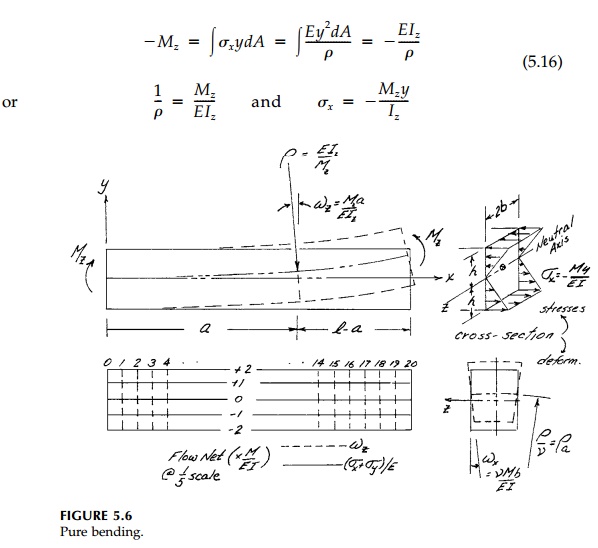
These are the standard formulae of elementary bending theory and are the exact free field if the surface tractions are distributed over the ends x = 0, l in the same way as the internal stresses σx.
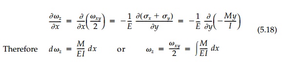
To determine the displacements for pure bending, the
relative displace-ments must be integrated. From the stress�'strain
relationships:
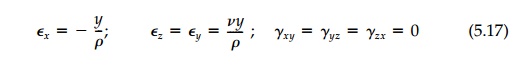
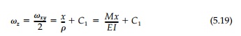
The elastic rotations can be found by drawing a flow
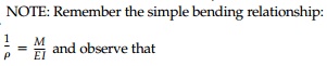
net as in Figure 5.6 or from the conjugate relationships. From Equation (4.13):
which are the basic differential and integral
relationships between the “slope diagram“ and the “moment diagram“ (derived
differently in a beginning strength-of-materials course). In this case where
the moment is constant:
Since this is a case of Plane Stress, Equation
(4.14) applies and
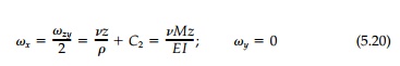
where from symmetry, C2 =0.
The arbitrary constants of integration must be determined from conditions on the geometry of deformations dictated by the support. Assuming no rotation, ωz, of the cross-section at x = 0 and no displacement of the origin, then C1 is zero as are all integration constants for u, v, and w. Thus from Equation (4.18):
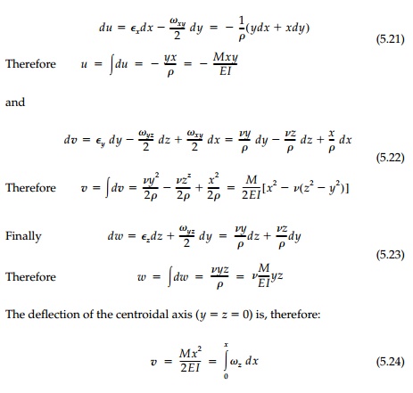
which is simply the
integral of the slope (rotation) diagram as given by the elementary theory.
Considering the deformation of any cross-section,
say at x = a, points on
the yz plane end up at:
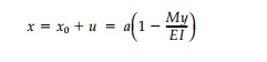
and, in fact, plane sections do remain plane as was
assumed. The in-plane deformation of the cross-section is shown in Figure 5.6.
After bending, the position of the vertical edges at z =+- b become
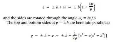
If the deformations are small and h < l , the parabolic curves are closely approximated by a circle with a radius of “anticlastic curvature“ ρa = ρ/v.
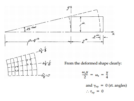
Example 5.1
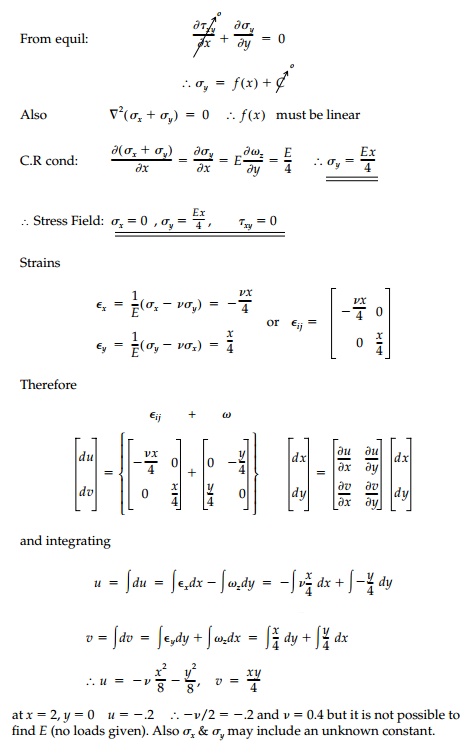
An element in a structure built of an elastic material displaces as shown below. Determine (if possible) a compatible elastic field (i.e., σij, Eij, ωij , ui). Assume plane stress and assume σx = 0. Can you determine elastic properties
of the material from this test? If so, do so.
there are, obviously, elastic rotations involved.
Use the engineering definition of strain and neglect body forces and any
nonlinearity due to large deformations.
Related Topics