Chapter: Microprocessor and Microcontroller : I/O Interfacing
Parallel Communication Interface: 8255 Programmable Peripheral Interface and Interfacing
Parallel Communication Interface:
8255 Programmable Peripheral Interface and Interfacing
The 8255 is a widely used, programmable parallel
I/O device. It can be programmed to transfer data under data under various
conditions, from simple I/O to interrupt I/O. It is flexible, versatile and
economical (when multiple I/O ports are required). It is an important general
purpose I/O device that can be used with almost any microprocessor.
The 8255
has 24 I/O pins that can be grouped primarily into two 8 bit parallel ports: A
and B, with the remaining 8 bits as Port C. The 8 bits of port C can be used as
individual bits or be grouped into two 4 bit ports: CUpper (CU) and CLower
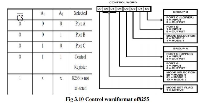
(CL). The functions of these ports are defined by writing a control word in the
control register.
8255 can
be used in two modes: Bit set/Reset (BSR) mode and I/O mode. The BSR mode is
used to set or reset the bits in port C. The I/O mode is further divided into 3
modes: mode 0, mode 1 and mode 2. In mode 0, all ports function as simple I/O
ports.
Mode 1 is
a handshake mode whereby Port A and/or Port B use bits from Port C as handshake
signals. In the handshake mode, two types of I/O data transfer can be
implemented: status check and interrupt. In mode 2, Port A can be set up for
bidirectional data transfer using handshake signals from Port C, and Port B can
be set up either in mode 0 or mode 1.
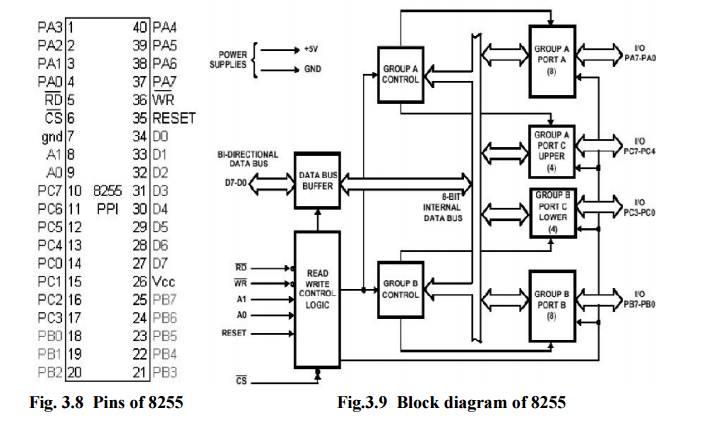
RD: (Read): This signal enables the Read
operation. When the signal is low, microprocessor
reads data from a selected I/O port of 8255.
WR: (Write): This control signal enables the
write operation.
RESET (Reset): It clears the control registers and sets all ports in input
mode. CS,A0, A1: These are device
select signals. is connected to a decoded address and A0, A1 are connected to A0, A1 of microprocessor.
ü I/O Modes
of 8255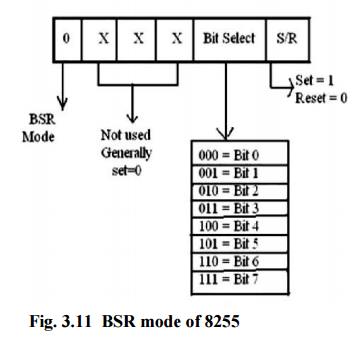
Mode 0: Simple Input or Output
In this
mode, Port A and Port B are used as two simple 8-bit I/O ports and Port C as
two4-bit I/O ports. Each port (or half-port, in case of Port C) can be
programmed to function as simply an input port or an output port. The
input/output features in mode 0 are: Outputs are latched, Inputs are not
latched. Ports do not have handshake or interrupt capability.
Mode 1: Input or Output with handshake
In mode
1, handshake signals are exchanged between the microprocessor and peripherals
prior to data transfer. The ports (A and B) function as 8-bit I/O ports. They
can be configured either as input or output ports. Each port (Port A and Port
B) uses 3 lines from port C as handshake signals. The remaining two lines of
port C can be used for simple I/O functions. Input and output data are latched
and Interrupt logic is supported.
Mode 1: Input control signals
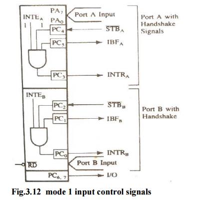
STB Strobe Input): This signal (active low)
is generated by a peripheral device that it has transmitted a byte of data. The
8255, in response to, generates IBF and INTR.
IBF (Input buffer full): This signal is an acknowledgement by the 8255
to indicate that the input latch has
received the data byte. This is reset when the microprocessor reads the data. INTR (Interrupt Request): This is an
output signal that may be used to interrupt the microprocessor. This signal is generated if , IBF and INTE are all
at logic 1.
INTE (Interrupt Enable): This is
an internal flip-flop to a port and needs to be set to generate the INTR signal. The two flip-flops INTEA and INTEB are
set /reset using the BSR mode. The INTEA is enabled or disabled through PC4,
and INTEB is enabled or disabled through PC2.
(Output Buffer Full): This is
an output signal that goes low when the microprocessor writes data into the output latch of the 8255. This signal
indicates to an output peripheral that new data is ready to be read. It goes
high again after the 8255 receives a signal from the peripheral.
(Acknowledge): This is an input signal
from a peripheral that must output a low when the peripheral receives the data
from the 8255 ports.
INTR (Interrupt Request): This is
an output signal, and it is set by the rising edge of the signal. This signal can be used to interrupt the microprocessor to
request the next data byte for output. The INTR is set and INTE are all one and
reset by the rising edge of . .
INTE (Interrupt Enable): This is
an internal flip-flop to a port and needs to be set to generate the INTR signal. The two flip-flops INTEA and INTEB are
set /reset using the BSR mode. The INTEA signal can be enabled or disabled
through PC6, and INTEB is enabled or disabled through PC2.
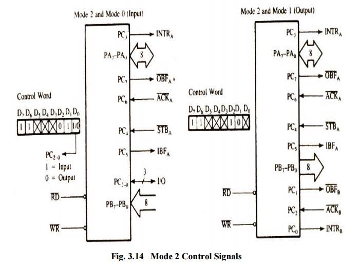
ü Mode 2:
Bidirectional Data Transfer
OBF This mode is used primarily in
applications such as data transfer between the two computers or floppy disk controller interface. Port A can be
configured as the bidirectional port and Port B either in mode 0 or mode 1.
Port A uses five signals from Port C as handshake signals for data transfer.
The remaining three lines from Port C can be used either as simple I/O or as
handshake signals for Port B.
Related Topics