Chapter: Aquaculture Engineering : Instrumentation and Monitoring
Monitoring systems - Aquaculture Engineering
Monitoring systems
On an aquaculture facility it is necessary to control all the different factors that are involved in the management of the farm. This can for instance be a water quality factor such as the concentration of oxygen, ensuring sufficient water flow, or the correct water level in a head basin. Of course this can be done with manual measurements and observations, but is very time-consuming if done with high regularity. How regularly measurements must be taken depends on the economic consequences if something fails. In intensive fish farming with high stock density and much use of technical installations that can fail, the need for regular measurement and control is obvious. The time available for remedial action when something fails is also limited. Systems for automatic control are there-fore used based on economic and practical consequences, especially in intensive fish farming. To illustrate this a land-based marine fish farm that requires pumping to supply water to the fish can be used as an example. The importance of continuous control of the water flow into the fish tanks is obvious.
A monitoring system comprises three major components (Fig. 19.16):
· Sensors and measuring equipment which control the conditions Monitoring centre which receives signals from the sensors and measuring equipment, interprets them and eventually sends out alarm signals or signals to regulators
· Equipment for warning when something is failing and emergency equipment that is started and stopped by regulators.
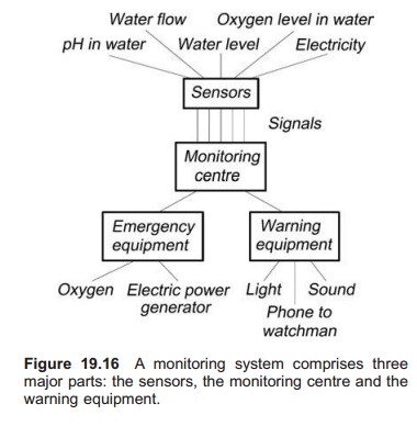
Signals are transferred between the components. These are normally electrical signals via cables; wireless connections however, may also be used. A monitoring centre is always equipped with a battery back-up so that it can always function indepen-dently whether or not there is an electricity supply.
Sensors and measuring equipment
To control the conditions a number of sensors which function as monitoring points in the alarm system can be used. Sensors can be used to control water level, water flows or water quality parameters, all described earlier in this chapter. Sensors are much used also to indicate whether the electricity supply is connected or not. The number of factors to be controlled determines the size of the monitoring system. From the sensors or measuring equipment electrical signals are sent to the monitoring centre: these can be digital signals, i.e. current or not current, for example from a level sensor where an electric circuit is broken and the signal to the monitoring centre changes from current to no current. The signal may also be analogues which means that the current coming into the monitoring centre varies depending on the value read from the sensor; an example of such an instrument is an oxygen meter. A current corresponding to the measured oxygen level is sent to the monitoring centre;
thus if the oxygen concentration decreases, less current flows. Normally this standardizes low current signals of between 4 and 20 mA.
Monitoring centre
The construction of the monitoring centre that receives the signals, interprets them and eventually sends out signals to the warning equipment, depends on the complexity of the system. Even though the monitoring centre is usually built especially for aquaculture facilities, it is based either on a programmable logic controller (PLC) or a computer.
A PLC can be visualized as an electronically operated switch system. It includes a number of input channels and a number of output channels. Electric signals from the sensors come through the input channels. The electrical output signals (i.e. how the switches are functioning) can be programmed based on the input signals. Programming of the PLC is done using an external keyboard con-nected to the ‘brain’ of the PLC. Whether output signals will be sent, and through which of the output channels, depends on the input signals and the location of the switch system. In and out signals can be digital or analogue, or most commonly both.
To illustrate the functioning of a PLC, take a simple monitoring system on a farm as an example. The farm equipment includes a pump that delivers water to a head tank from which it flows under gravity to the fish tanks. Pure oxygen gas from an oxygen bottle can be added to the single fish tanks through diffusers at the bottom of the tanks. The following measuring instruments are included: a level sensor in the head tank and an oxygen sensor in each of the fish tanks. In addition there is a reserve pump on stand-by, a magnetic valve that controls the emergency oxygen supply, and a siren available on the farm.
The programme for the PLC might be as follows. If the water level in the head tank is too low a signal will go from the level sensor to the PLC. The PLC is then programmed to send an output signal to the reserve pump to start it. If the oxygen level in the tank is too low, the value input to the PLC is under a programmed value and a signal is sent out through the channel that controls the magnetic valve on the oxygen gas bottle. This will change from the closed to the open position. In addition, a signal is sent to the channel that starts the siren.
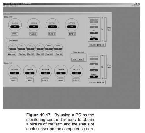
If a computer is used as a monitoring centre it is normally equipped with special cards known as I/O cards or data acquisition cards (DAQ) that make it possible to import signals, including analogue signals, and send out the same types of signals as the PLC. By using a computer the input signals can easily be recorded and stored. It is also possible to get a hard copy of the time points for alarms, including which of the sensors registered the failure. It is also possible to get a picture of the farm, including the sensors and their individual status, on the computer screen, which makes visual control of operations easier (Fig. 19.17). Today, both PLC and PC are used in combined systems.
Warning equipment
From the monitoring centre electric signals are sent through the output channels to external warning equipment. The warning equipment is installed on the farm and normally includes both equipment that creates light and sound, such as warning lights and sirens. A telephone may also be included in the system. This dials fixed programmed phone numbers, among others to the watchman’s mobile phone. On more advanced systems, a message saying what is wrong appears on the telephone display
Regulation equipment
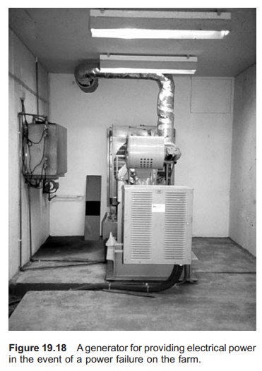
The signals may also be used to start emergency equipment or to regulate the functioning of equipment. For instance, in the event of a power failure, a generator will start (Fig. 19.8). The equipment may also open emergency oxygen supplies to the fish tanks or start stand-by pumps. Often there is a combination of starting emergency equipment and starting external warning equipment.
Maintenance and control
For a monitoring system to be reliable it is very important to carry out proper maintenance and testing. The maintenance normally includes testing and calibration of the sensors. It is advisable to have a fixed routine for testing the monitoring system, for instance once a week. The sensors are then tested to ensure that the signals being emitted and also that the signals are being sent from the centre to the warning equipment. Emergency systems such as electric generators and systems for adding oxygen must also be tested at fixed intervals, to be sure that they will function if a real emergency sit-uation occurs.
Related Topics