Chapter: Aquaculture Engineering : Instrumentation and Monitoring
Instruments for measuring physical conditions - Aquaculture Engineering
Instruments for measuring physical conditions
There are many places were there is a need to control physical conditions. In aquaculture, the water condition is of major importance, particularly the following factors: water flow, water level and water pressure. Many methods can be used to measure these parameters; some can also be used to measure more than one. There are differences both in price and accuracy of available instruments. Methods used are reviewed below; for more information see, for instance, refs 9 and 11.
Measuring the water flow
It is a common practice to measure water flow to be sure that it is constant and that the correct amount of water passes through the pipes. Water flow measurements can be carried out at various places in a fish farm. Flow meters may be located in the main inlet pipe, in part flow pipes or in the inlet pipe to a single tank. Several principles are actually used, such water as velocity and head loss. The methods used to measured the flow in open channels and pipes are different. The main empha-sis here is on measurement in pipes that are full of water, since this is the most common situation in fish farming. Some of the methods presented may, however, also be used in open channels.
Measuring water velocity
The water velocity is proportional to water flow. If the water velocity and the inter-nal diameter of the pipe are known, it is easy to calculate the water flow.
A simple way to measure the water velocity in a pipe is to use a propeller, paddle wheel or turbine (Fig. 19.5). Propellers with a variety of designs are used. The working principle is that the water will move the propeller and the rotational velocity of the propeller will reflect the water velocity in the pipe. Either the propeller can be installed in an existing pipe system, known as an inset meter, or it can be a completely separate system in which the propeller and instruments are connected, forming a complete unit adapted to the pipe. Propeller systems are simple and inexpensive, but one of the disadvantages is that the head loss will increase.
However, the main disadvantage is that the propeller will be exposed to fouling because it is within the water flow. Normally, fouling will reduce the measured velocity compared with the actual velocity. Correct maintenance is therefore important in such a system. A further disadvantage is wear of the continuously moving propeller.
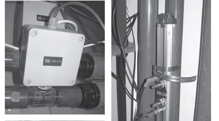
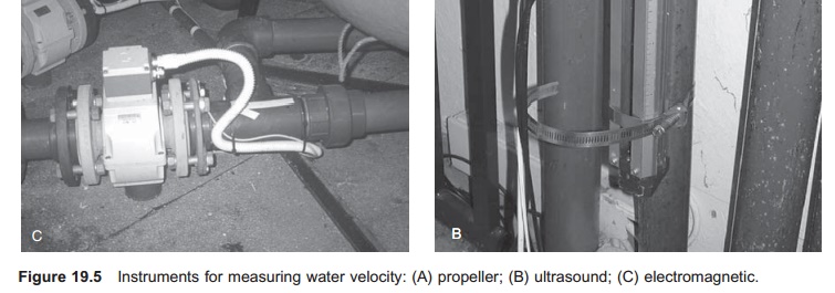
An electromagnetic flow meter can also be used to measure water velocity (Fig. 19.5). The principle utilized here is that an electromagnetic field changes when the water velocity varies. A conducting fluid, such as water, in a magnetic field will induce an electric voltage, which correlates with the water velocity. The water must have some electrical conductivity if this type of instrument is to function; in fish farming this will always be the case.
Ultrasound waves may also be used for measuring the water flow, as in an ultrasonic flow meter (Fig. 19.5). Two combined ultrasound source and receiver units are placed, one on each side of the pipe and crossed diagonally. Sound waves are sent from one side and travel with the water flow; from the opposite side of the pipe another sound wave is sent against direction of the water flow. The times taken for the sound waves to reach the receivers are compared; the water velocity can be calculated because the water flow deflects the sound waves and alters their velocity. A fixed unidirectional ultrasonic system can also be used which calculates the time difference during which the sound waves travel. The advantage of this system is that the instrument may be attached to the exterior of existing pipes; if the type of pipe is known the water flow inside can be found. Flow meters utilizing this principle will not give any head loss and are very accurate; however, they are quite expensive. The instruments may also be affected by air bubbles or high particle concentrations.
The various types of flow meter have different accuracies, and this must be checked before selection. Generally, greater accuracy incurs greater expenditure, so the meter must be fit for purpose.
Measuring head loss
Head loss in a pipe will occur when the water passes an obstruction in the pipe or any other object that reduce the water flow. Measurement of the head loss may therefore be used to calculate the water velocity, since the head loss depends on the velocity; an increase in velocity will increase the head loss. When this principle is used for flow measurements, a known obstruction is set inside the pipe. A very accurate plate with a hole in the centre, slightly smaller than the internal pipe diameter, known as an orifice plate, is usually used (Fig. 19.6). The difference in the pressure before and after the plate gives an indirect measurement of the water flow. This instrument is also called a differential pressure flow meter. The physical relation used when measuring the head loss is defined by the Bernoulli equation:

Where:
p=pressure
ρ =density
v =velocity
h=elevation (height)
g=acceleration due to gravity.
The disadvantage with this method is that a head loss occurs, especially with the orifice plate, so instead a venturi can be used which functions in the same way, but the head loss is reduced.
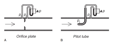
Another instrument based on measuring the differential pressure (actually the head loss) to calculate water flow is the pitot tube which measures the dynamic head (total head) and the static head (Fig. 19.6). Based on the difference between these two values, the water velocity can be calculated (from the Bernoulli equation). Correct use of this is important because there is a velocity pro-file inside the pipe that must be taken into consideration when locating the pitot tube.
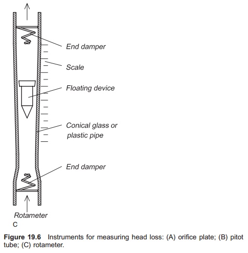
A rotameter or hover velocity meter also utilizes the head loss measurement, but with a constant head loss. The construction of a rotameter includes a conical glass or plastic pipe, with a floating device inside (Fig. 19.6); this device is lifted when the water starts to flow. Since the pipe is conical the height by which the floating device is lifted will depend on the magnitude of the water flow, because the area where the waters is flowing is increased. A normal rotameter must be placed vertically to function. In a similar instrument the device is set on a spring with known characteristics, and this is compressed when the water flows by an amount that depends on the water flow. Vertical installation is not necessary for this flow meter.
Measuring water pressure
Water pressure is measured to control water levels in tanks or the pressure in pipes. If the pressure is too high or low a warning signal can be given.
Diaphragm manometers are often used to measure the water pressure. The principle is that pressure can alter the shape of a diaphragm (Fig. 19.7). An increase in pressure will change the form of the diaphragm and this change can be used to control an indicator. The manometer is fixed directly to the pipe where the measurements are taken.
A bourdon tube manometer may also be used for pressure measurements (Fig. 19.7). This system consists of a hollow bent pipe that is connected directly to the place where the pressure is measured. When the pressure increases, the bent pipe will try to straighten as the pressure is considerably higher on the outside of the bend than on the inside because
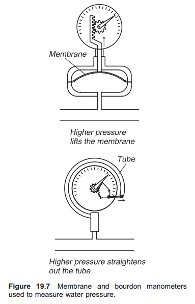
the area where the force acts is larger; this movement will be registered on a scale calibrated to show the pressure. There are also other devices using the same principle, such as pressure capsules and bellows.
Today, however, the most commonly used instruments are electronic load cells or pressure transducers. They function because there is a small change in the electric resistance in an electric circuit related to the pressure. A pressure transducer may be installed on the bottom of a tank or inside a pipe.
Measuring water level
Measuring the water level is necessary at various places to avoid overflows and water shortages. This can be carried out in a head tank or directly in the individual fish tanks. Water level sensors are normally digital, sending a signal if the level of the water is below or above defined values. The system may also be analogue; this generates a signal that is proportional to the water level.
Different types of electronic floats may be used for controlling the water level. The float will lie on the surface and change position if the water level varies; this variation can be utilized to control the level. When this happens a signal will be sent and action taken, for instance switching the water supply on and off. A commonly used float is the level rocking sensor (Fig. 19.8) which floats on the surface; if the water level decreases it will gradually become more upright. The sensor is located in the
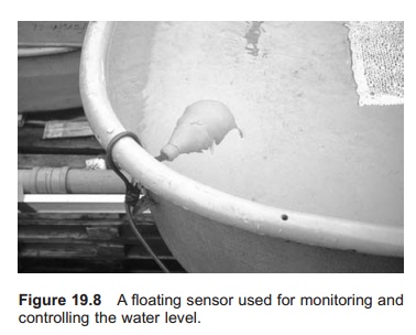
end of a cable and when it is in the floating position there may or may not be contact between the two conductors located inside the float. If the sensor is hanging vertically an automatic switch will take the opposite position (opened or closed as the case may be) to make or break the electric circuit. This can then be used to control the water level. On submerged pumps this is a common method for starting and stopping the pumping, depending on the water level.
Other methods are also used to measure the water level in fish farms, of which pressure sensors, as described above, are the most common.
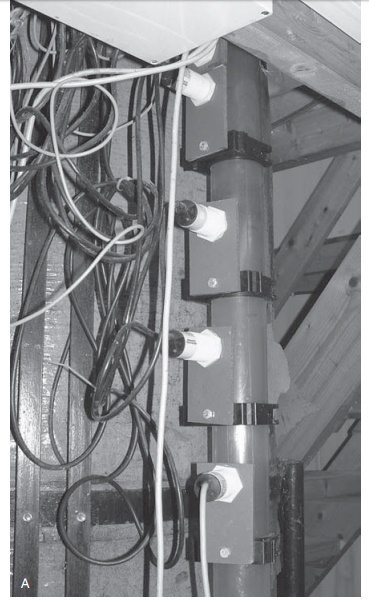
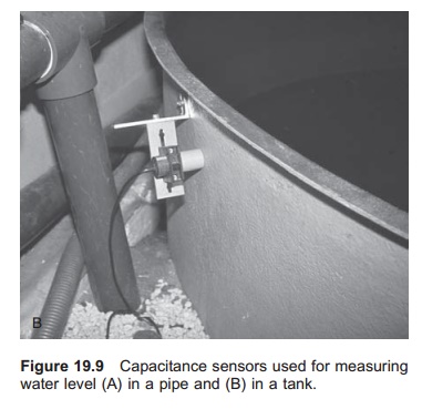
Capacitance sensors are becoming popular for monitoring water levels (Fig. 19.9). These sensors detect how well a material keeps its electrical charge. Water may keep 80 times as much electrical charge compared to air and the sensor can there-fore register changes in electrical charges associated with changes in water level. If the tank wall is thin, the sensor may be placed on the outside of the tank wall and will be capable of sensing whether the tank is filled with water or not. If the water level decreases to beneath the position of the sensor, an electrical circuit will be either opened or closed and a signal given.
Water level can be controlled very accurately by ultrasound devices A transmitter and receiver are placed above the water surface. By transmitting a sound wave and measuring the time of reflection with the receiver, it is possible to calculate the distance from the transmitter to the water surface and hence the water level. If the water level decreases, the time taken by the sound wave to travel between the transmitter and receiver will increase.
Related Topics