Chapter: Measurements and Instrumentation : Comparison Methods of Measurements
Maxwell bridge: Definition, Circuit Diagram, Explanation, Advantages and Disadvantages

Maxwell bridge
Definition
A Maxwell bridge (in long form, a Maxwell-Wien bridge) is a type of Wheatstone bridge used to measure an unknown inductance (usually of low Q value) in terms of calibrated resistance and capacitance. It is a real product bridge.
The maxwell bridge is used to measure unknown inductance in terms of calibrated resistance and capacitance. Calibration-grade inductors are more difficult to manufacture than capacitors of similar precision, and so the use of a simple "symmetrical" inductance bridge is not always practical.
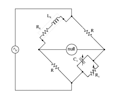
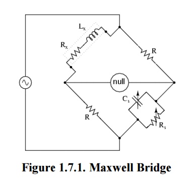
Circuit Diagram

Explanation
With reference to the picture, in a typical application R1 and R4 are known fixed entities, and R2 and C2 are known variable entities.
R2 and C2 are adjusted until the bridge is balanced.R3 and L3 can then be calculated based on the values of the other components:
As shown in Figure, one arm of the Maxwell bridge consists of a capacitor in parallel with a resistor (C1 and R2) and another arm consists of an inductor L1 in series with a resistor (L1 and R4). The other two arms just consist of a resistor each (R1 and R3).
The values of R1 and R3 are known, and R2 and C1 are both adjustable. The unknown values are those of L1 and R4.
Like other bridge circuits, the measuring ability of a Maxwell Bridge depends on 'Balancing' the circuit.
Balancing the circuit in Figure 1 means adjusting C1 and R2 until the current through the bridge between points A and B becomes zero. This happens when the voltages at points A and B are equal.
Mathematically,
Z1 = R2 + 1/ (2πfC1); while Z2 = R4 + 2πfL1.
(R2 + 1/ (2πfC1)) / R1 = R3 / [R4 + 2πfL1];
or
R1R3 = [R2 + 1/ (2πfC1)] [R4 + 2πfL1]
To avoid the difficulties associated with determining the precise value of a variable capacitance, sometimes a fixed-value capacitor will be installed and more than one resistor will be made variable.
The additional complexity of using a Maxwell bridge over simpler bridge types is warranted in circumstances where either the mutual inductance between the load and the known bridge entities, or stray electromagnetic interference, distorts the measurement results.
The capacitive reactance in the bridge will exactly oppose the inductive reactance of the load when the bridge is balanced, allowing the load's resistance and reactance to be reliably determined.
Advantages:
The frequency does not appear
Wide range of inductance
Disadvantages:
Limited measurement
It requires variable standard capacitor
Related Topics