Chapter: Measurements and Instrumentation : Comparison Methods of Measurements
Hay Bridge: Definition, Circuit Diagram, Explanation, Advantages and Disadvantages

HAY BRIDGE
Definition
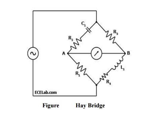
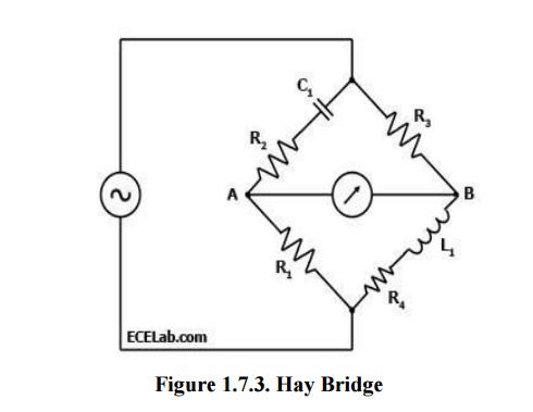
A Hay Bridge is an AC bridge circuit used for measuring an unknown inductance by balancing the loads of its four arms, one of which contains the unknown inductance. One of the arms of a Hay Bridge has a capacitor of known characteristics, which is the principal component used for determining the unknown inductance value. Figure 1 below shows a diagram of the Hay Bridge.
Explanation
As shown in Figure 1, one arm of the Hay bridge consists of a capacitor in series with a resistor (C1 and R2) and another arm consists of an inductor L1in series with a resistor (L1 and R4).
The other two arms simply contain a resistor each (R1 and R3). The values of R1and R3 are known, and R2 and C1 are both adjustable.
The unknown values are those of L1 and R4.
Like other bridge circuits, the measuring ability of a Hay Bridge depends on 'balancing' the circuit.
Balancing the circuit in Figure 1 means adjusting R2 and C1 until the current through the ammeter between points A and B becomes zero. This happens when the voltages at points A and B are equal.
Diagram

When the Hay Bridge is balanced, it follows that Z1/R1 = R3/Z2 wherein Z1 is the impedance of the arm containing C1 and R2 while Z2 is the impedance of the arm containing L1 and R4.
Thus, Z1 = R2 + 1/(2πfC) while Z2 = R4 + 2πfL1.
[R2 + 1/(2πfC1)] / R1 = R3 / [R4 + 2πfL1]; or
[R4 + 2πfL1] = R3R1 / [R2 + 1/(2πfC1)]; or
R3R1 = R2R4 + 2πfL1R2 + R4/2πfC1 + L1/C1.
When the bridge is balanced, the reactive components are equal, so
2πfL1R2 = R4/2πfC1, or R4 = (2πf) 2L1R2C1.
Substituting R4, one comes up with the following equation:
R3R1 = (R2+1/2πfC1) ((2πf) 2L1R2C1) + 2πfL1R2 + L1/C1; or
L1 = R3R1C1 / (2πf) 2R22C12 + 4πfC1R2 + 1);
L1 = R3R1C1 / [1 + (2πfR2C1)2]
After dropping the reactive components of the equation since the bridge is
Thus, the equations for L1 and R4 for the Hay Bridge in Figure 1 when it is balanced are:
L1 = R3R1C1 / [1 + (2πfR2C1)2]; and
R4 = (2πfC1)2R2R3R1 / [1 + (2πfR2C1)2]
Advantages:
Simple expression
Disadvantages:
It is not suited for measurement of coil
Related Topics