Chapter: Special Electrical Machines : Permanent Magnet Brushless D.C. Motors
Magnetic Circuit Analysis on Open Circuit
MAGNETIC CIRCUIT ANALYSIS ON OPEN
CIRCUIT
Cross
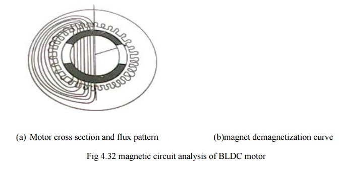
section of a 2 pole brushless dc motor having high energy rare earth magnets on
the rotor and the demagnetization curve are as shown in fig 4.32 (a & b)

First
step to analyze a magnetic circuit is to identify the main flux paths and the
reluctance or permeances assigned to them.
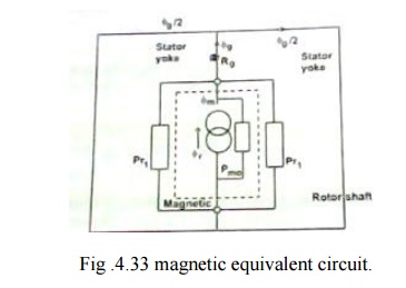
The
equivalent magnetic circuit is shown in fig 4.33.only half of the equivalent
circuit is shown & the lower half is the mirror image of the upper half
about the horizontal axis, which is at equipotential. This assumption is true
only if the two halves are balanced. If not the horizontal axis might still be
an equipotential but the fluxes and the magnetic potentials in the two halves
would be different and there could be residual flux in the axial direction
.along the shaft. The axial flux is undesirable because it can induce current
to flow in the bearing.

The steel
cores of the stator and rotor shaft are assumed to be infinitely permeable.
Each
magnet is represented by a ŌĆŚNortonŌĆś equivalent circuit consisting of a flux
generator in parallel with an internal leakage permeance pmo.
Žģr=BrAm ŌĆ”ŌĆ”.(4.43)
Pmo=╬╝0╬╝recAm/lm ŌĆ”ŌĆ”.(4.44)
where Am ŌĆō pole area the magnet
lm ŌĆō
length of the magnet in the direction of magnetization (in this case its radial
thickness)
Br-
remanent flux density
╬╝rec-
relative recoil permeability (the slope of the demagnetization curve)
In this
case the outer pole area is larger than the inner pole area but to keep the
analysis simple average pole area is considered.
with a
magnet arc of 120┬░
Am=2/3ß┤©[r1ŌĆōg-lm/2]l ŌĆ”ŌĆ”ŌĆ”.(4.45)
r1-
radius of the rotor
g- air
gap length
most of
the magnet flux crosses the air gap via the air gap reluctance Rg
Rg=gŌĆś/╬╝0Ag ŌĆ”ŌĆ”ŌĆ”..(4.46)
gŌĆś-
equivalent air gap length allowing for slotting.
the
slotting can be taken into account by means of carterŌĆśs coefficient, which
case,
gŌĆś=Kc g ŌĆ”ŌĆ”ŌĆ”ŌĆ”ŌĆ”ŌĆ”ŌĆ”ŌĆ”ŌĆ”...(4.47)
Ag- air
gap area through which the flux passes as it crosses he gap . the precise
boundary of this area is uncertain because of fringing both at the edges of the
magnet and at the ends of the rotor.An approximate allowance for fringing can
be made by adding ŌĆŚgŌĆś at each of the four boundaries ,giving
Ag=[2/3 (r1- g/2)+2g](l+2g) ŌĆ”..(4.48)
’üČ the
remaining permeance in the magnetic circuit I the rotor leakage permeance Žürl,
which represents the paths of the magnet flux components that fails to cross
the air gap. this can be conveniently included in a modified magnet internal
permeance by writing
pm=pmo+prl ŌĆ”ŌĆ”ŌĆ”ŌĆ”(4.49(a))
pm=pmo(1+prl) ŌĆ”ŌĆ”.(4.49(b))
prl-normalized
rotor leakage permeance
Related Topics