Chapter: Special Electrical Machines : Permanent Magnet Brushless D.C. Motors
Commutation in Motors With 120┬░ and 180┬░ Magnet Arc
COMMUTATION IN MOTORS WITH 120┬░
AND 180┬░ MAGNET ARC
BLPM dc
motor with 180┬░ magnet arcs and 120┬░ square wave phase currents arc shown in
fig. 4.23 and 4.24.
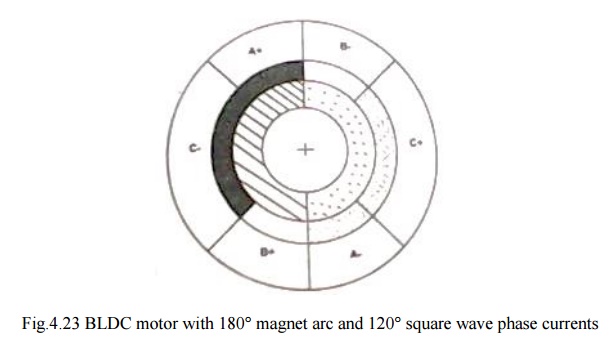
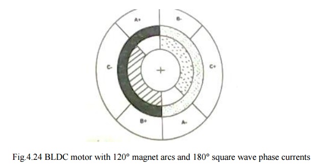
In Fig.
4.26 the rotor magnet poles are shaded to distinguish north and south. The
phase belts are shaded us complete 60┬░ sector of the stator bore. There are two
slots in each of these phase belts. The current in these two slots are identical
and conductors in them are in series
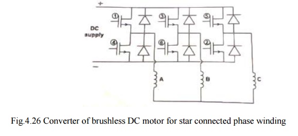
Between the rotor ring and the stationary belt ring in fig. 4.26 there is a third ring called the ŌĆ¢mmf ringŌĆ¢. This represents the mmf distribution of the stator currents at a particular instant.
v At the
instant shown wt=0, phase A is conducting positive current and phase C is
conducting negative current. The resulting mmf distribution has the same shading
as the N and S rotor poles to indicate the generation of torque,
v Where the
mmf distribution has like shasing, positive torque is produced. Where mmf and
flux shading are unlike, negative torque is produced. Where one is zero, no
torque is zero, no torque is produced. The total torque is the integral of the
contributions from around the entire air gap periphery.
The rotor is rotating in the clockwise direction.
After 60┬║ of rotation, the rotor poles start to ŌĆŚuncoverŌĆś the C phase belts and
the torque contribution of phase C starts to decrease linearly.
During this period, the magnet poles, have been 'coveringŌĆś the B phase belts. Now if the negative current is commutated from C
to B exactly at then point 60┬║, then the torque will be unaffected and will
continue constant for a further 60┬║. After 120┬║, positive current must be
commutated from A to C.
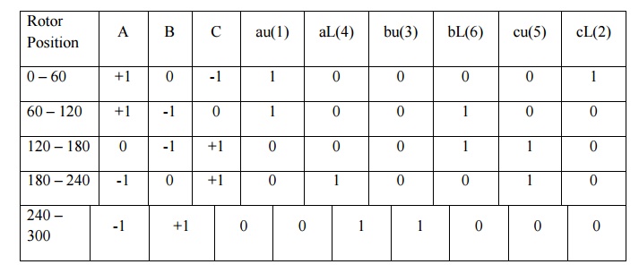
Commutation
tables for three-phase brushless dc motors.
TABLE 4.1 180┬║ Magnet-Star
Winding. 120┬║ Square wave phase Currents

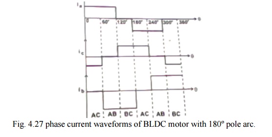
v The
production of smooth, ripple free torque depends on the fact the magnet pole
arc exceeds the mmf arc by 60┬║.
v Here only
2/3 of the magnet and 2/3 of the stator conductors are active at any instant
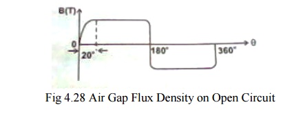
In a
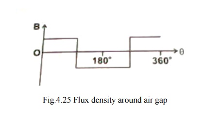
practical motor the magnet flux-density distribution cannot be perfectly
rectangular as shown in fig.4.27. for a highly coercive magnets and full 180┬║
magnet arcs there is a transition section of the order of 10-20┬║ in width. This
is due to fringing effect. Likewise on the stator side, the mmf distribution is
not rectangular but have a stepped wave form as shown in fig.4.28 that reflects
the slotting.
To some
extent these effects cancel each other so that s that satisfactory results are
obtained with a magnet arc as short as 150┬║, and two slots per pole per phase.
But there
is always dip in the torque in the neighborhood of the commutation angles. This
torque dip occurs every 60┬║ elec degrees, giving rise to a torque ripple
component with a fundamental frequency equal to 6P times the rotation frequency
where P is the number of pole pairs. The magnitude and width of the torque dip
depends on the time taken to commutate the phase current.
Phase
current waveforms corresponding to high speed and low speed operations are as
shown in fig. 4.29 (a & b)
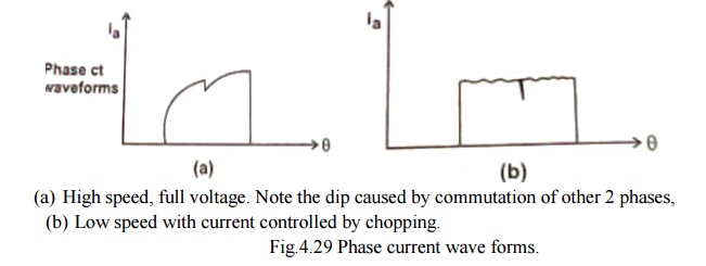
(a) High
speed, full voltage. Note the dip caused by commutation of other 2 phases,
(b) Low speed
with current controlled by chopping.
Fig.4.29
Phase current wave forms.
v The back
emf is of equal value in the incoming phase and is in such a direction as to
oppose the current build up.
v While the
flux distribution of the magnet rotates in a continuous fashion, the mmf
distribution of the stator remains stationary for 60┬║ and then jumps to a
position 60┬║ ahead.
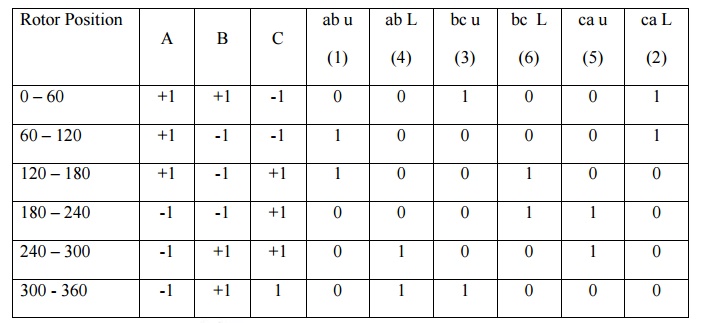
Similar
analysis is made with a motor having 120 ┬║ pole arc magnets with delta
connected armature winding.
Table 4.2 120┬║ Magnet Delta
Winding, 180┬║ Square Wave Phase Currents.
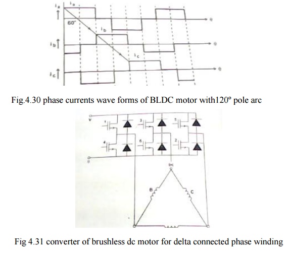
v C phase
belt remains covered by the magnet poles. While the coverage of A phase belt
increases thereby decreasing that of B phase belt.
v Since all
the conductors are varying same current the increasing torque contribution of
phase A is balancing by the decreasing contribution of phase B. Therefore, the
total torque remains constant.
v Similarly
there is a linear increase in the back emf of A and equal and oppoaite decrease
in the back emf in phase B, Therefore the back emf at the terminals remains
constant.
v Line
current divides equally between two paths One-phase C Second-phase A & B
series.
This
balance is not perfect in practice because of the resistance and inductance of
the windings.But the current balance should be maintained, otherwise
circulating current may produce excessive torque ripple and additional losses.
When
compared with 180┬░ pole arc machine.
v For the
same ampere-conductors per slot and for the same peak flux density, the 120┬░
pole arc machine has 1.5 times copper losses, but produces the same torque.
v Also the
ampere-conductors per slot would have to be reduced because the duty cycle is
1.0 instead of 2/3.
Merits
v For the
same magnet flux density the total flux is only 2/3 of that of 180┬░ pole arc
motor, so that only 2/3 of the stator yoke thickness is required. If the stator
outside diameter is kept the same, the slots can be made deeper so that the
loss of ampere conductors can be at least partially covered .consequently the
efficiency of the motor may not be very much less than that of 180┬░ pole arc
machine.
v In this
machine also, the effects of fringing flux, slotting and communication overlap
combine to produce torque ripple.
v Only emf
and torque are discussed. The concept of hanging flux-linkage and energy
balance can also be used to analyze the operation.
Related Topics