Chapter: Special Electrical Machines : Permanent Magnet Brushless D.C. Motors
Emf Equation of BLPM SQW DC Motors
EMF EQUATION OF BLPM SQW DC
MOTORS
The basic
torque emf equations of the brushless dc motor are quite simple and resemble
those of the dc commutator motor.
The
co-ordinate axis have been chosen so that the center of a north pole of the
magnetic is aligned with the x-axis at ė© = 0 .the stator has 12 slots and a
three phasing winding. Thus there are two slots per pole per phase.
v Consider a BLPM SQW DC MOTOR
Let ŌĆśpŌĆśbe
the number of poles (PM)
ŌĆśBgŌĆś
be the flux density in the air gap in wb/m2.
Bk
is assumed to be constant over the entire pole pitch in the air gap (180įÄ
pole arc)
ŌĆśrŌĆś be
the radius of the airgap in m.
ŌĆślŌĆś be
the length of the armature in m.
ŌĆśTcŌĆś
be the number of turns per coil.
ŌĆśŽēmŌĆś
be the uniform angular velocity of the rotor in mechanical rad/sec.
Žēm=2ŽĆN/60
where N is the speed in rpm.
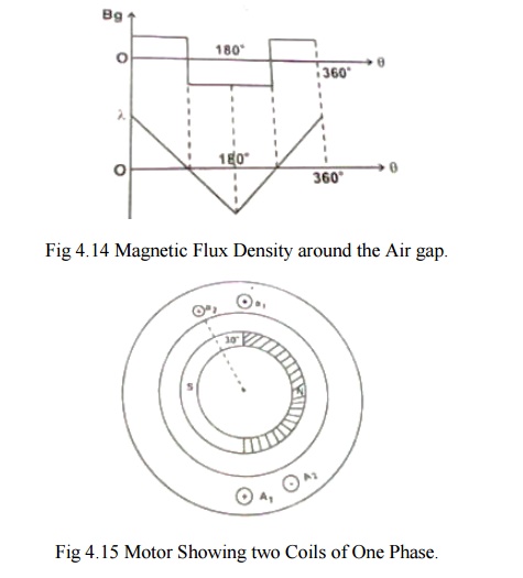
Flux
density distribution in the air gap is as shown in fig 4.14.At t=0(it is
assumed that the axis of the coil coincides with the axis of the permanent
magnet at time t=0).
Let at Žēmt=0,the
centre of N-pole magnet is aligned with x-axis.
At Žēmt=0,x-axis
is along PM axis.
Therefore
flux enclosed by the coli is
╬”max=B x 2ŽĆr/p x l ŌĆ”ŌĆ”ŌĆ”ŌĆ”ŌĆ”ŌĆ”...(4.1)
=flux/pole
╬”max=rlŌł½0ŽĆ
B(╬Ė)d╬Ė
=Bg
rl[╬Ė]0ŽĆ
=Bgrl[ŽĆ]
At Žēmt=0,the
flux linkage of the coil is
╬ømax=
(Bg x 2ŽĆr/p x l)Tc Žēb-T ŌĆ”ŌĆ”ŌĆ”ŌĆ”ŌĆ”ŌĆ”ŌĆ”ŌĆ”.(4.2)
Let the
rotor rotating in ccw direction and when Žēmt=ŽĆ/2, the flux enclosed
by the coil ╬”, Therefore ╬╗=0.
The flux
linkages of the coil vary with ╬Ė variation of the flux linkage is as shown
above.
The flux
linkages of the coil changes from BgrlTcŽĆ/p at Žēmt=0
(i.e) t= 0 t0 ╬Ė at t=ŽĆ/pŽēm.
Change of
flux linkage of the coil (i.e) Ōłå╬╗ is
Ōłå╬╗/Ōłåt
=Final flux linkage ŌĆō Initial flux linkage/time.
=0- (2BgrlTcŽĆ/p)/
(ŽĆ/pŽēm)
= -(2BgrlTcŽēm) ŌĆ”ŌĆ”ŌĆ”ŌĆ”ŌĆ”ŌĆ”ŌĆ”ŌĆ”ŌĆ”ŌĆ”...(4.3)
The emf
induced in the coil ec= - d╬╗/dt
ec
=2BgrlTcŽēm ŌĆ”ŌĆ”ŌĆ”ŌĆ”ŌĆ”ŌĆ”ŌĆ”ŌĆ”ŌĆ”ŌĆ”ŌĆ”.(4.4)
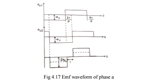
Distribution
of ec with respect to t is shown in fig 4.16
It is
seen that the emf waveform is rectangular and it toggles between + ec
to - ec. The period of the wave is 2ŽĆr/pŽēm sec and
magnitude of ec is
ec
=2BgrlTcŽēm volts ŌĆ”ŌĆ”ŌĆ”ŌĆ”ŌĆ”ŌĆ”ŌĆ”ŌĆ”ŌĆ”ŌĆ”ŌĆ”ŌĆ”...(4.5)
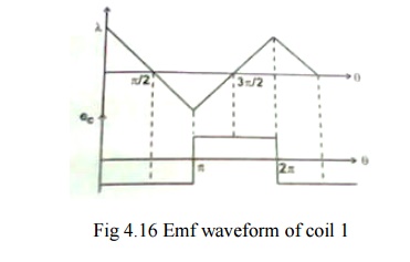
Consider
two coils a1A1 and a2A2 as shown in fig 5.15.Coil a2A2 is adjacent to a1A1 is
displaced from a1A1 by an angle 30įÄ(i.e.) slot angle ŽÆ .
The
magnitude of emf induced in the coil a1A1
ec2 =BgrlTcŽēm
volts ŌĆ”ŌĆ”ŌĆ”ŌĆ”ŌĆ”ŌĆ”ŌĆ”ŌĆ”ŌĆ”ŌĆ”ŌĆ”.(4.6)
The
magnitude of emf induced in the coil a2A2
ec2 =BgrlTcŽēm
volts ŌĆ”ŌĆ”ŌĆ”ŌĆ”ŌĆ”ŌĆ”ŌĆ”ŌĆ”ŌĆ”ŌĆ”...(4.7)
Its emf
waveform is also rectangular but displaced by the emf of waveform of coil ec1
by slot angle ŽÆ .
If the
two coils are connected in series, the total phase voltage is the sum of the
two separate coil voltages.
ec1 +ec2 =2BgrlTcŽēm ŌĆ”ŌĆ”ŌĆ”ŌĆ”ŌĆ”ŌĆ”ŌĆ”ŌĆ”ŌĆ”ŌĆ”ŌĆ”ŌĆ”..(4.8)
Let nc be the number of coils that are
connected in series per phase ncTc =Tph be the
number of
turns/phase.
eph=
nc [2BgrlTcŽēm ] ŌĆ”ŌĆ”ŌĆ”ŌĆ”ŌĆ”ŌĆ”ŌĆ”ŌĆ”ŌĆ”ŌĆ”ŌĆ”ŌĆ”.(4.9)
eph=
2BgrlTphŽēm volts ŌĆ”ŌĆ”ŌĆ”ŌĆ”ŌĆ”ŌĆ”ŌĆ”ŌĆ”ŌĆ”ŌĆ”ŌĆ”ŌĆ”..(4.10)
eph=resultant
emf when all nc coils are connected in series.
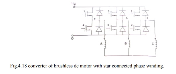
The
waveforms are as shown in fig 4.17
The
waveform of eph is stepped and its amplitude is 2BgrlTphŽēm
volts.
At any instant 2-phase windings are connected in
series across the supply terminals as shown in fig 4.18.
Assumption
Armature winding is Y connected.
Electronic switches are so operated using rotor position sensor that the resultant emfs across the winding terminals is always = 2 eph.
Amplitude of back emf generated in Y connected armature winding E = 2 eph.
Related Topics