Chapter: Digital Electronics : Minimization Techniques and Logic Gates
Logic Gates
LOGIC GATES:
In Boolean algebra, there are three basic logic operations: AND, OR, and NOT. These logic gates are digital circuits constructed from diodes, transistors, and resistors connected in such a way that the circuit output is the result of a basic logic operation (OR, AND, NOT) performed on the inputs.
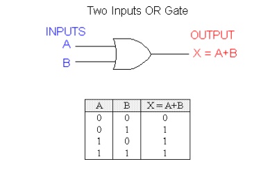
OR OPERATION
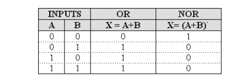
The expression X = A + B reads as "X equals A OR B". The + sign stands for the OR operation, not for ordinary addition.
The OR operation produces a result of 1 when any of the input variable is 1.
The OR operation produces a result of 0 only when all the input variables are 0.
An example of three input OR gate and its truth table is as follows:
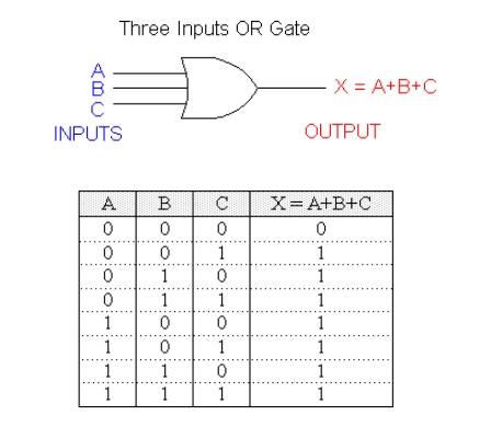
With the OR operation, 1 + 1 = 1, 1+ 1 + 1 = 1 and so on.
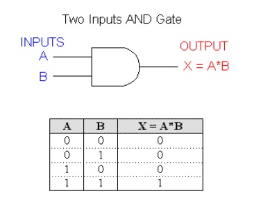
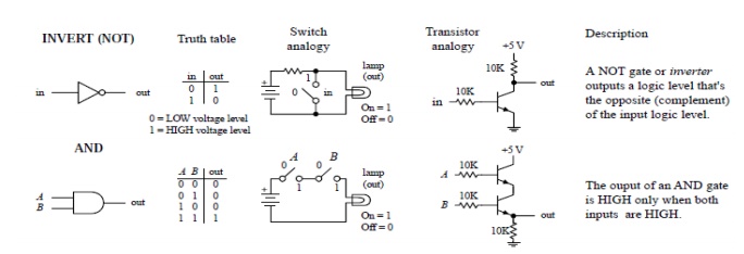
AND Operation
The expression X = A * B reads as "X equals A AND B". The multiplication sign stands for the AND operation, same for ordinary multiplication of 1s and 0s.The AND operation produces a result of 1 occurs only for the single case when all of the input variables are 1.The output is 0 for any case where one or more inputs are 0.
An example of three input AND gate and its truth table is as follows:
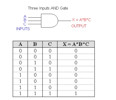
With the AND operation, 1*1 = 1, 1*1*1 = 1 and so on.
NOT Operation
The NOT operation is unlike the OR and AND operations in that it can be performed on a single input variable. For example, if the variable A is subjected to the NOT operation, the result x can be expressed as x = A' where the prime (') represents the NOT operation. This expression is read as:
x equals NOT A
x equals the inverse of A
x equals the complement of A
Each of these is in common usage and all indicate that the logic value of x = A' is opposite to the logic value of A. The truth table of the NOT operation is as follows:
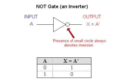
1'=0 because NOT 1 is 0
0' = 1 because NOT 0 is 1
The NOT operation is also referred to as inversion or complementation, and these terms are used interchangeably.
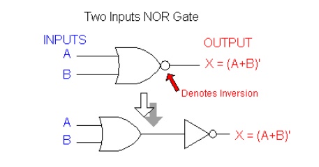
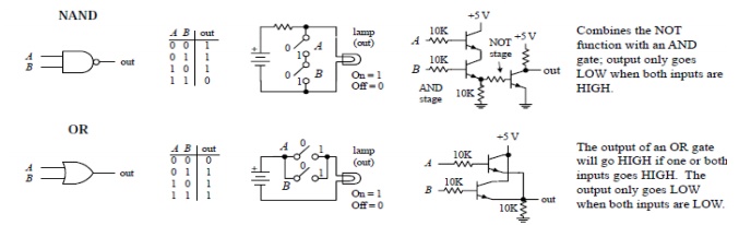
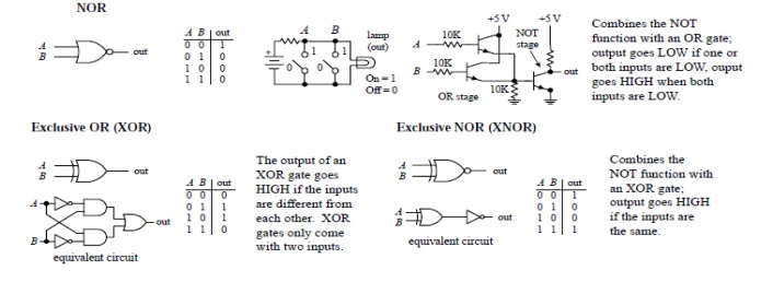
NOR Operation
NOR and NAND gates are used extensively in digital circuitry. These gates combine the basic operations AND, OR and NOT, which make it relatively easy to describe then using Boolean algebra. NOR gate symbol is the same as the OR gate symbol except that it has a small circle on the output. This small circle represents the inversion operation. Therefore the output expression of the two input NOR gate is:
X = (A + B)'
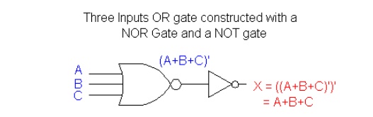
An example of three inputs OR gate can be constructed by a NOR gate plus a NOT gate:
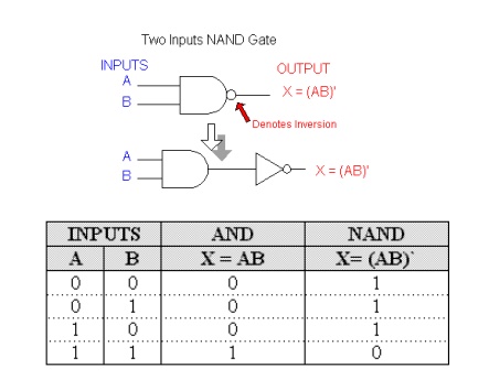
NAND Operation
NAND gate symbol is the same as the AND gate symbol except that it has a small circle on the output. This small circle represents the inversion operation. Therefore the output expression of the two input NAND gate is:
X = (AB)'
Ex-NOR Gate Equivalent
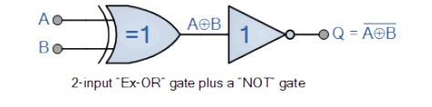
The Exclusive-NOR Gate function is achieved by combining standard gates together to form more complex gate functions and an example of a 2-input Exclusive-NOR gate is given below.
The Digital Logic “Ex-NOR” Gate
2-input Ex-NOR Gate
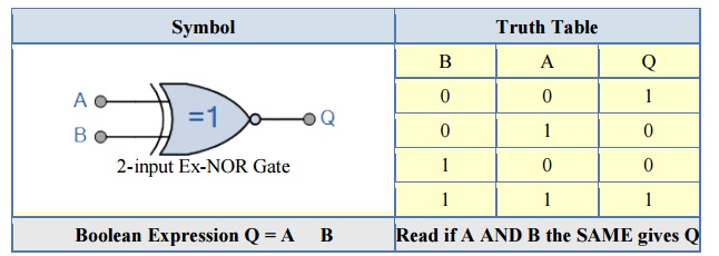
The logic function implemented by a 2-input Ex-NOR gate is given as “when both A AND B are the SAME” will give an output at Q. In general, an Exclusive-NOR gate will give an output value of logic “1” ONLY when there are an EVEN number of 1’s on the inputs to the gate (the inverse of the Ex-ORgate) except when all its inputs are “LOW”.
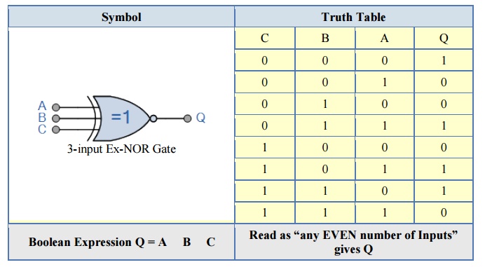
Then an Ex-NOR function with more than two inputs is called an “even function” or modulo-2-sum (Mod-2-SUM), not an Ex-NOR. This description can be expanded to apply to any number of individual inputs as shown below for a 3-input Exclusive-NOR gate.
3-input Ex-NOR Gate
Exclusive-OR Gate
2-input Ex-OR Gate
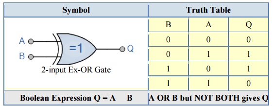
The truth table above shows that the output of an Exclusive-OR gate ONLY goes “HIGH” when both of its two input terminals are at “DIFFERENT” logic levels with respect to each other. If these two inputs, A and B are both at logic level “1” or both at logic level “0” the output is a “0” making the gate an “odd but not the even gate”.
This ability of the Exclusive-OR gate to compare two logic levels and produce an output value dependent upon the input condition is very useful in computational logic circuits as it gives us the following Boolean expression of:
Q = (A B) = A.B + A.B
The logic function implemented by a 2-input Ex-OR is given as either: “A OR B but NOT both” will give an output at Q. In general, an Ex-OR gate will give an output value of logic “1” ONLY when there are an ODD number of 1’s on the inputs to the gate, if the two numbers are equal, the output is “0”.
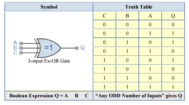
Then an Ex-OR function with more than two inputs is called an “odd function” or modulo-2-sum (Mod-2-SUM), not an Ex-OR. This description can be expanded to apply to any number of individual inputs as shown below for a 3-input Ex-OR gate.
3-input Ex-OR Gate
Related Topics