Chapter: Civil Surveying : Theodolite Surveying
Locating Landscape Details with the Theodolite

Locating Landscape Details with the
Theodolite
We
have discussed so far methods to survey the main frame or the skeleton of the
survey. In most surveys, it is necessary to locate details such as buildings,
railway lines, canals, and other landmarks along with the survey. A transit
with a steel tape is used to locate details, and many methods are available, as
the transit is an angle-measuring instrument. The following methods can be
used.
Angle and
distance from a single station
A
point can be located with an angle to the station along with the distance from
that station as shown in Fig. 6.28(a). The angle is preferably measured from
the same reference line to avoid confusion. A sketch with the line and the
distance and angle measured will help in plotting later. A road can be located
as shown in Fig. 6.28(b). Angles to a number of points are measured and with
each angle two distances are measured to locate the road.
Angle from one
station and distance from another
If
for any reason, it is not possible to measure the angle and distance to an
object from the same point, it may be possible to locate the point by measuring
angles from one station and distances from the other. The recorded data should
clearly indicate the stations from which the angle and distance are measured.
Figure 6.28(c) shows this method of measuring. The angle is measured from
station A to point P. When the instrument is shifted to B, the distance to
point P is measured from B with a steel tape.
Angles from two
stations
If
for some reason, it is not possible to measure distances, then angles from two
stations are enough to locate a point. As shown in Fig. 6.28(d), the point P is
located by measuring angles to point P from stations A and B.
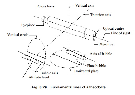
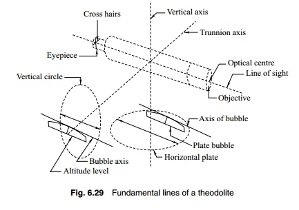
The following are the fundamental lines.
1. The vertical axis
2. The horizontal or trunnion axis
3. The line of collimation or line of sight
4. Axis of altitude level
5. Axis of plate level
The meaning of these terms has been discussed earlier. The axes
are shown in Fig. 6.29. When the instrument is properly adjusted, the
relationships between these axes are the following.
(a) The horizontal axis must be perpendicular to the vertical axis.
(b) The axis of the plate level must be perpendicular to the vertical
axis.
(c) The line of collimation must be at right angles to the horizontal
axis.
(d) The axis of the altitude level (and telescope level) must be
parallel to the line of collimation.
(e) The vertical circle vernier must read zero when the line of sight
is horizon-tal.
Each one of
these relations gives conditions for accurate measurement.
(a) When the horizontal axis is perpendicular to the vertical axis,
the line of sight generates a vertical plane when transited.
(b) When the axis of the plate level is perpendicular to the vertical
axis, the vertical axis will be truly vertical when the bubble traverses.
(c) When the line of collimation is at right angles to the horizontal
axis, the tele-scope when rotated about the horizontal axis will move in a
vertical plane.
(d) When the line of collimation and the axis of altitude level are
parallel, the vertical angles will be measured without any index error.
(e) The index error due to the displacement of the vernier is eliminated when the vernier reads zero with the line of collimation truly horizontal.

Related Topics