Chapter: Civil Surveying : Theodolite Surveying
Theodolite: Horizontal Motion, Vertical Motion
THEODOLITE
A theodolite is essentially a transit of high precision. Theodolites come in different sizes and weights and from different manufacturers. Although theodolites may differ in appearance, they are basically alike in their essential parts and operation. Some of the models currently available for use in the military are WILD (Herrbrugg), BRUNSON, K&E, (Keuffel & Esser), and PATH theodolites.
To give you an idea of how a theodolite differs from a transit, we will discuss some of the most commonly used theodolites in the U.S. Armed Forces.
One-Minute Theodolite
The 1-min directional theodolite is essentially a directional type of instrument. This type of instrument can be used, however, to observe horizontal and vertical angles, as a transit does.
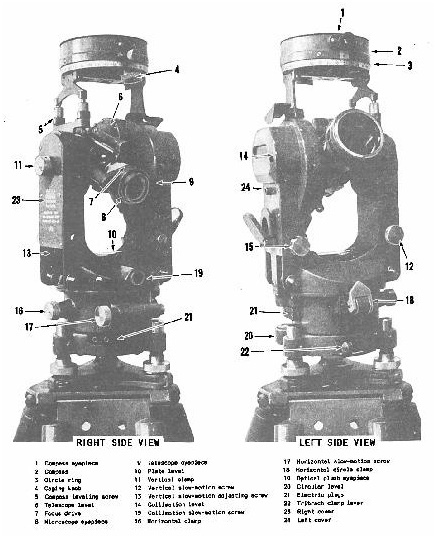
The theodolite shown in figure 11-12 is a compact, lightweight, dustproof, optical reading instrument. The scales read directly to the nearest minute or 0.2 mil and are illuminated by either natural or artificial light. The main or essential parts of this type of theodolite are discussed in the next several paragraphs.
HORIZONTAL MOTION
Located on the lower portion of the alidade, and adjacent to each other, are the horizontal motion clamp and tangent screw used for moving the theodolite in azimuth. Located on the horizontal circle casting is a horizontal circle clamp that fastens the circle to the alidade. When this horizontal (repeating) circle clamp is in the lever-down position, the horizontal circle turns with the telescope. With the circle clamp in the lever-up position, the circle is unclamped and the telescope turns independently. This combination permits use of the theodolite as a REPEATING INSTRUMENT. To use the theodolite as a DIRECTIONAL TYPE OF INSTRUMENT, you should use the circle clamp only to set the initial reading. You should set an initial reading of 0 o 30´ on the plates when a direct and reverse (D/R) pointing is required. This
will minimize the possibility of ending the D/R pointing with a negative value.
VERTICAL MOTION
.- Located on the standard opposite the vertical circle are the vertical motion clamp and tangent screw. The tangent screw is located on the lower left and at right angles to the clamp. The telescope can be rotated in the vertical plane completely around the axis (360 o ).
LEVELS.- The level vials on a theodolite are the circular, the plate, the vertical circle, and the telescope level. The CIRCULAR LEVEL is located on the tribrach of the instrument and is used to roughly level the instrument. The PLATE LEVEL, located between the two standards, is used for leveling the instrument in the horizontal plane. The VERTICAL CIRCLE LEVEL (vertical collimation) vial is often referred to as a split bubble. This level vial is completely built in, adjacent to the vertical circle, and viewed through a prism and 450
mirror system from the eyepiece end of the telescope. This results in the viewing of one-half of each end of the bubble at the same time. Leveling consists of bringing the two halves together into exact coincidence, as
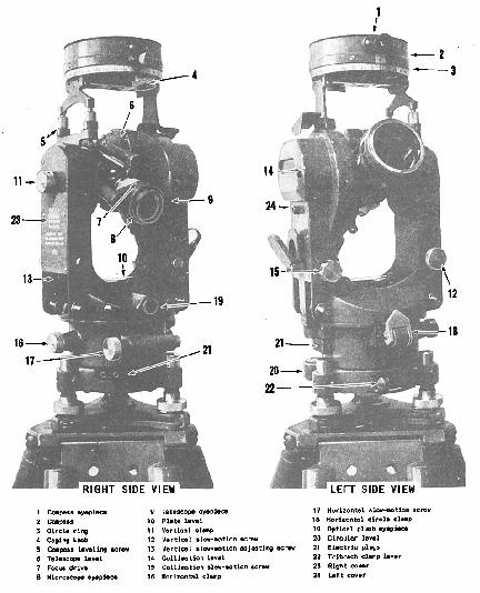
Figure 11-12.-One-minute theodolite.
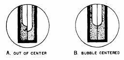
Figure 11-13.-Coincidence- type level.
shown in figure 11-13. The TELESCOPE LEVEL, mounted below the telescope, uses a
prism system and a 450 mirror for leveling operations. When the telescope is plunged to the reverse position, the level assembly is brought to the top.
TELESCOPE.- The telescope of a theodolite can be rotated around the horizontal axis for direct and reverse readings. It is a 28-power instrument with the shortest focusing distance of about 1.4 meters. The cross wires are focused by turning the eyepiece; the image, by turning the focusing ring. The reticle (fig. 11-14) has horizontal and vertical cross wires, a set of vertical and horizontal ticks (at a stadia ratio of 1:100), and a solar circle on the reticle for
making solar observations. This circle covers 31 min of arc and can be imposed on the sun's image (32 min of arc) to make the pointing refer to the sun'scenter. One-half of the vertical
line is split for finer centering on small distant objects.
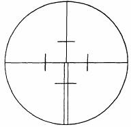
Figure 11-14.-Theodolite reticle.
The telescope of the theodolite is an inverted image type. Its cross wires can be illuminated by either sunlight reflected by mirrors or by battery source. The amount of illumination for the telescope can be adjusted by changing the position of the illumination mirror.
TRIBRACH.- The tribrach assembly (fig. 11-15), found on most makes and models, is a detachable part of the theodolite that contains the leveling screw, the circular level, and the optical plumbing device. A locking device holds the alidade and the tribrach together and permits interchanging of instruments without moving
the tripod. In a "leapfrog" method, the instrument (alidade) is detached after observations are completed. It is then moved to the next station and another tribrach. This procedure reduces the amount of instrument setup time by half.
CIRCLES.- The theodolite circles are read through an optical microscope. The eyepiece is located to the right of the telescope in the direct position, and to the left, in the reverse. The microscope consists of a series of lenses and prisms that bring both the horizontal and the
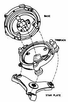
Figure 11-15.-Three-screw leveling head.
vertical circle images into a single field of view. In the DEGREE-GRADUATED SCALES (fig. 11-16), the images of both circles are shown as they would appear through the microscope of the 1-min theodolite. Both circles are graduated from 0 o to 360 o with an index graduation for each degree on the main scales. This scale'sgraduation appears to be superimposed over an auxiliary that is graduated in minutes to cover a span of 60 min (1 o ). The position of the degree mark on the auxiliary scale is used as an index to get a direct reading in degrees and minutes. If necessary, these scales can be interpolated to the nearest 0.2 min of arc.
The vertical circle reads 0 o when the theodolite'stelescope is pointed at the zenith, and 180 o
when it is pointed straight down. A level line reads 90 o in the direct position and 2700 in the reverse. The values read from the vertical circle are referred to as ZENITH DISTANCES and not vertical angles. Figure 11-17 shows how these zenith distances can be converted into vertical angles.

Figure 11-16.-Degree-graduated scales.
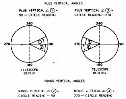
Figure 11-17.-Converting zenith distances into vertical angles (degrees).
In the MIL-GRADUATED SCALES (fig. 11-18), the images of both circles are shown as they would appear through the reading micro-scope of the 0.2-mil theodolite. Both circles are graduated from 0 to 6,400 mils. The main scales are marked and numbered every 10 mils, with the
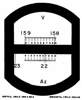
Figure 11-18.-Mil-graduated scales.
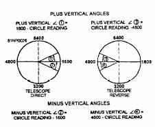
Figure 11-19.-Vertical angles from zenith distances (mils).
last zero dropped. The auxiliary scales are graduated from 0 to 10 roils in 0.2-mil increments. Readings on the auxiliary scale can be interpolated to 0.1 mil. The vertical circle reads 0 mil when the telescope is pointed at the zenith, and 3,200 mils when it is pointed straight down. A level line reads 1,600 roils in the direct position and 4,800 roils in the reverse. The values read are zenith distances. These zenith distances can be converted into vertical angles as shown in figure 11-1
The excavation of material in underwater areas is called dredging, and a dredge is an excavator afloat on a barge. A dredge may get itself into position by cross bearings, taken from the dredge on objects of known location on the beach, or by some other piloting method. Many times, however, dredges are positioned by survey triangulation. The method of determining direction angles from base line control points is the same as that just described.
Related Topics