Chapter: Mechanical : Dynamics of Machines : Force Analysis
Klien’s Construction
KLIEN’S CONSTRUCTION
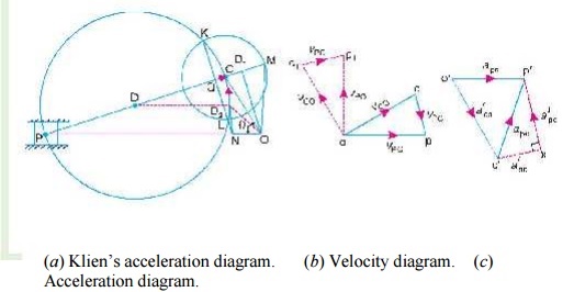
Let OC be the crank and PC the connecting rod of a reciprocating steam engine, as shown in Fig. 15.2 (a). Let the crank makes an angle θ with the line of stroke PO and rotates with uniform angular velocity ω rad/s in a clockwise direction. The Klien’s velocity and acceleration diagrams are drawn as discussed below:

Fig. 15.2. Klien’s construction.
1 Klien’s velocity diagram
First of all, draw OM perpendicular to OP; such that it intersects the line PC produced at M. The triangle OCM is known asKlien’s velocity diagram. In this triangle OCM,
OM may be regarded as a line perpendicular to PO,
CM may be regarded as a line parallel to PC, and ...(Q It is the same line.)
CO may be regarded as a line parallel to CO.
We have already discussed that the velocity diagram for given configuration is a triangle ocp as shown in Fig. 15.2 (b). If this triangle is revolved through 90°, it will be a triangle oc1 p1, in which oc1 represents vCO (i.e. velocity of C with respect to O or velocity of crank pin C) and is paralel to OC,
op1 represents vPO (i.e. velocity of P with respect to O or velocity of cross-head or piston P) and is perpendicular to OP, and c1p1 represents vPC (i.e. velocity of P with respect to C) and is parallel to CP.
A little consideration will show, that the triangles oc1p1 and OCM are similar. Therefore,
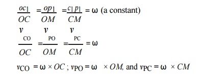
Thus, we see that by drawing the Klien’s velocity diagram, the velocities of various points may be obtained without drawing a separate velocity diagram.
2 Klien’s acceleration diagram
The Klien’s acceleration dia-gram is drawn as discussed below:
1. First of all, draw a circle with C as centre and CM as radius.
2. Draw another circle with PC as diameter. Let this circle inter-
sect the previous circle at K and L.
3. Join KL and produce it to intersect PO at N. Let KL intersect PC at Q.
This forms the quadrilateral CQNO, which is known as Klien’s acceleration diagram.
We have already discussed that the acceleration diagram for the given configuration is as shown in Fig. 15. 2 (c). We know that
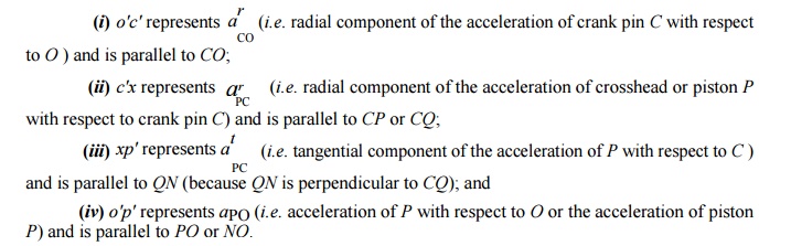
A little consideration will show that the quadrilateral o'c'x p' [Fig. 15.2 (c)] is similar to quadrilateral CQNO [Fig. 15.2 (a)]. Therefore,
SOLVED PROBLEMS
1.
The crank and connecting rod of a reciprocating
engine are 200 mm and 700 mm respectively. The crank is rotating in clockwise
direction at 120 rad/s. Find with the help of Klein’s construction: 1. Velocity and acceleration of the
piston, 2. Velocity and acceleration
of the mid point of the connecting rod, and 3. Angular velocity and angular acceleration of the connecting rod,
at the instant when the crank is at 30° to I.D.C. (inner
dead centre).
Solution. Given: OC = 200 mm = 0.2 m ; PC = 700 mm = 0.7 m ; ω = 120 rad/s
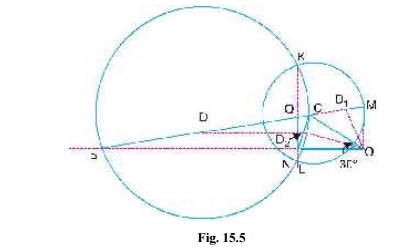
The Klein’s velocity diagram OCM
and Klein’s acceleration diagram CQNO
as shown in Fig. 15.5 is drawn to some suitable scale, in the similar way as
discussed in Art. 15.5. By measurement, we find that
OM = 127 mm = 0.127 m ; CM = 173
mm = 0.173 m ; QN = 93 mm = 0.093 m ; NO = 200 mm = 0.2 m
1. Velocity and acceleration of
the piston
We know that the velocity of the piston P,
vP = ω × OM
= 120 √ó 0.127 = 15.24 m/s Ans. and
acceleration of the piston P,
aP = ω 2 × NO = (120)2 × 0.2 =
2880 m/s 2 Ans.
2. Velocity and acceleration of
the mid-point of the connecting rod
In order to find the velocity of the mid-point D of the connecting rod, divide CM
at D1 in the same ratio as D divides CP. Since D is the
mid-point of CP, therefore D1 is the mid-point of CM,
i.e. CD1 = D1M. Join OD1. By measurement,
OD1 =
140 mm = 0.14 m
Velocity of D,
vD = ω × OD1 = 120 × 0.14 = 16.8 m/s Ans.
In order
to find the acceleration of the mid-point of the connecting rod, draw a line DD2 parallel to the line of stroke PO which intersects CN at D2. By measurement,
OD2 =
193 mm = 0.193 m ∴ Acceleration of D,
aD = ω 2 × OD2 = (120)2 ×
0.193 = 2779.2 m/s 2 Ans. 3.
Angular velocity and angular acceleration
of the connecting rod
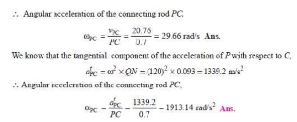
We know that the velocity of the connecting rod PC (i.e.
velocity of P with respect to C),
vPC = ω × CM =
120 √ó 0.173 = 20.76 m/s
Related Topics