Chapter: Mechanical : Dynamics of Machines : Force Analysis
Flywheel
FLYWHEEL
A flywheel used in machines serves as a reservoir, which stores energy
during the period when the supply of energy is more than the requirement, and
releases it during the period when the requirement of energy is more than the
supply.
In case of steam engines, internal combustion engines, reciprocating
compressors and pumps, the energy is developed during one stroke and the engine
is to run for the whole cycle on the energy produced during this one stroke.
For example, in internal combustion engines, the energy is developed only
during expansion or power stroke which is much more than the engine load and no
energy is being developed during suction, compression and exhaust strokes in
case of four stroke engines and during compression in case of two stroke engines.
The excess energy developed during power stroke is absorbed by the flywheel and
releases it to the crankshaft during other strokes in which no energy is
developed, thus rotating the crankshaft at a uniform speed. A little
consideration will show that when the flywheel absorbs energy, its speed
increases and when it releases energy, the speed decreases. Hence a flywheel
does not maintain a constant speed, it simply reduces the fluctuation of speed.
In other words, a flywheel controls the speed variations caused by the
fluctuation of the engine turning moment during each cycle of operation.
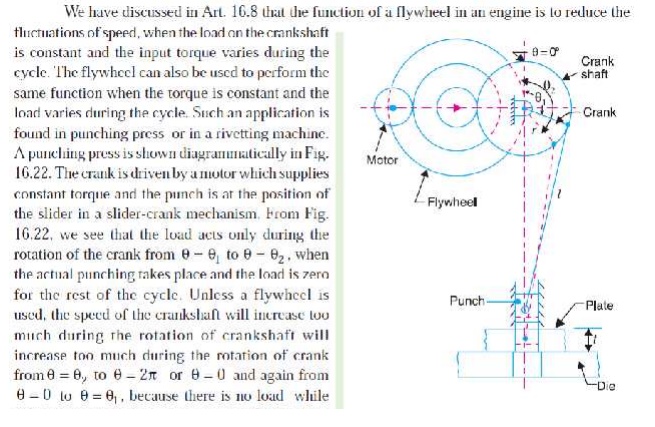
In
machines where the operation is intermittent like *punching machines, shearing
machines, rivetting machines, crushers, etc., the flywheel stores energy from
the power source during the greater portion of the operating cycle and gives it
up during a small period of the cycle. Thus, the energy from the power source
to the machines is supplied practically at a constant rate throughout the
operation.
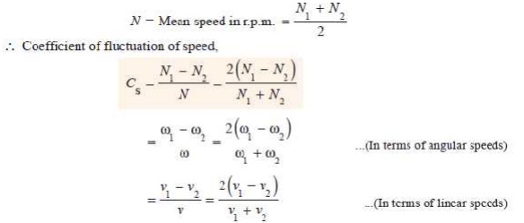
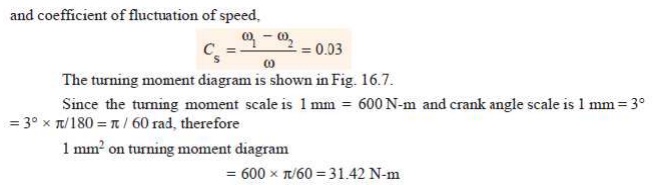
COEFFICIENT OF FLUCTUATION OF SPEED
The difference between the maximum and minimum speeds during a cycle is
called the maximum fluctuation of speed . The ratio of the maximum
fluctuation of speed to the mean speed is called the coefficient
of fluctuation of speed.
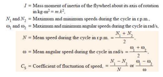
Let N1 and N2 = Maximum and minimum speeds in r.p.m.
during the cycle, and
The coefficient of fluctuation of speed is a limiting factor in the
design of flywheel. It varies depending upon the nature of service to which the
flywheel is employed.
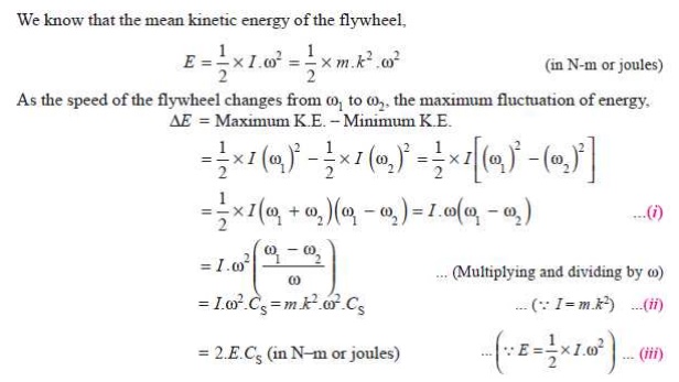
ENERGY STORED IN A FLYWHEEL
A flywheel is shown in Fig. 16.5. We have discussed in Art. 16.5 that
when a flywheel absorbs energy, its speed increases and when it gives up
energy, its speed decreases.
Let
m = Mass of the flywheel
in kg,
k = Radius of gyration of the flywheel
in metres,
The radius
of gyration (k) may be taken equal to
the mean radius of the rim (R),
because the thickness of rim is very small as compared to the diameter of rim.
Therefore, substituting k = R, in equation (ii), we have

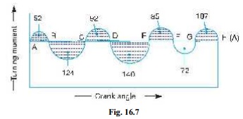
Q. The
turning moment diagram for a multicylinder engine has been drawn to a scale 1
m m = 600 N -m vertically and 1 m m = 3┬░ horizontally. The intercepted areas between the output torque curve and the mean
resistance line, taken in order from
one end, are as follows :
+ 52, ŌĆō 124, + 92, ŌĆō 140, + 85, ŌĆō 72 and + 107 m m2, when the engine is running at a speed of 600 r.p.m. If the total fluctuation of speed is not to exceed (-+) 1.5% of the mean, find the necessary mass of the flywheel of radius 0.5 m.
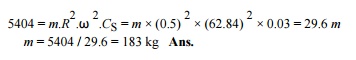
Solution. Given : N = 600 r.p.m. or Žē = 2 ŽĆ ├Ś 600 / 60 = 62.84 rad / s ; R
= 0.5 m
Since the
total fluctuation of speed is not to exceed (-+) 1.5% of the mean
speed, therefore Žē 1 ŌĆō Žē 2 = 3% Žē = 0.03 Žē
Let the
total energy at A = E, then referring to Fig. 16.7,
Energy at
B = E + 52 ...(Maximum
energy)
Energy at
C = E + 52 ŌĆō 124 = E ŌĆō 72
Energy at
D = E ŌĆō 72 + 92 = E + 20
Energy at
E = E + 20 ŌĆō 140 = E ŌĆō 120 ...(Minimum energy)
Energy at
F = E ŌĆō 120 + 85 = E ŌĆō 35
Energy at
G = E ŌĆō 35 ŌĆō 72 = E ŌĆō 107
Energy at
H = E ŌĆō 107 + 107 = E = Energy at A
We know
that maximum fluctuation of energy,
ŌłåE = Maximum energy ŌĆō Minimum energy
= (E + 52) ŌĆō (E ŌĆō 120) = 172 = 172 ├Ś 31.42
= 5404 N-m
Let m =
Mass of the flywheel in kg. We know that maximum fluctuation of energy (Ōłå E ),
Q. A shaft fitted with a flywheel rotates at 250
r.p.m. and drives a machine. The
torque of machine varies in a cyclic manner over a period of 3 revolutions. The torque rises from 750 N-m to 3000 N-m uniformly during 1/2 revolution and remains constant for the
following revolution. It then falls
uniformly to 750 N-m during the next
1/2 revolution and remains constant for one revolution, the cycle being repeated thereafter.
Determine the power required to drive the
machine and percentage fluctuation in speed, if the driving torque applied to
the shaft is constant and the mass of the flywheel is 500 kg with radius of
gyration of 600 m m.
Solution. Given : N = 250 r.p.m. or Žē = 2ŽĆ ├Ś 250/60 = 26.2 rad/s ; m = 500 kg ; k
= 600 mm = 0.6 m
The turning moment diagram for the complete
cycle is shown in Fig. 16.8. We know that the torque required for one complete
cycle
= Area of figure OABCDEF
=Area OAEF + Area ABG + Area BCHG + Area CDH
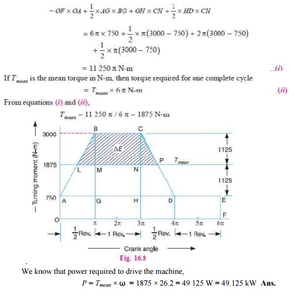
Power
required to drive the machine
We know that power required to drive the
machine,
P = Tmean ├Ś Žē = 1875 ├Ś 26.2 = 49 125 W = 49.125 kW
Ans.
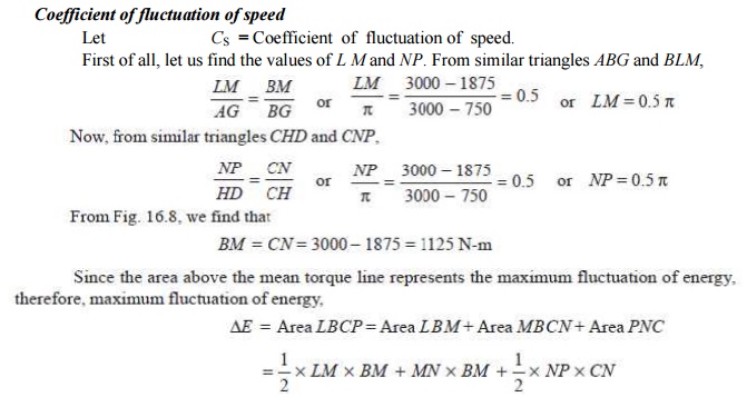
Coefficient
of fluctuation of speed
Let CS = Coefficient of fluctuation of speed.
First of
all, let us find the values of L M
and NP. From similar triangles ABG and BLM,

Solution. Given : P = 20 kW = 20 ├Ś 10 3 W; N = 300 r.p.m. or Žē = 2ŽĆ ├Ś 300/60 = 31.42 rad/s
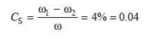
Since the total fluctuation of speed (Žē 1 ŌĆō Žē 2) is not to exceed ┬▒ 2 per cent of the mean speed ), therefore
Žē 1 ŌĆō Žē 2 = 4% Žē
and
coefficient of fluctuation of speed,
The
turning moment-crank angle diagram for a four stroke engine is shown in Fig.
16.11. It is assumed to be triangular during compression and expansion strokes,
neglecting the suction and exhaust strokes.
We know
that for a four stroke engine, number of working strokes per cycle,
n = N/2 =
300 / 2 = 150
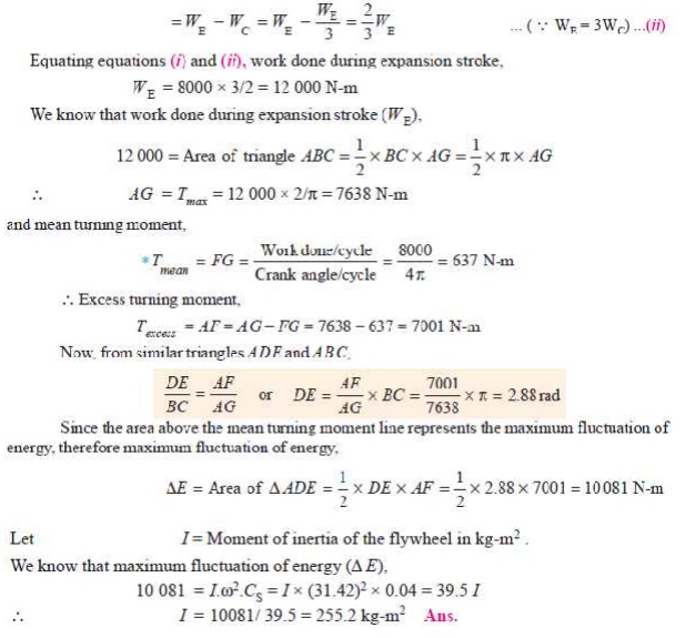
Ōł┤ Work
done/cycle =P ├Ś 60/ n = 20 ├Ś 10 3 ├Ś 60/150 = 8000 N-m ------------(i)
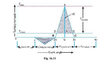
Since the
work done during suction and exhaust strokes is negligible, therefore net work
done per cycle (during compression and expansion strokes)
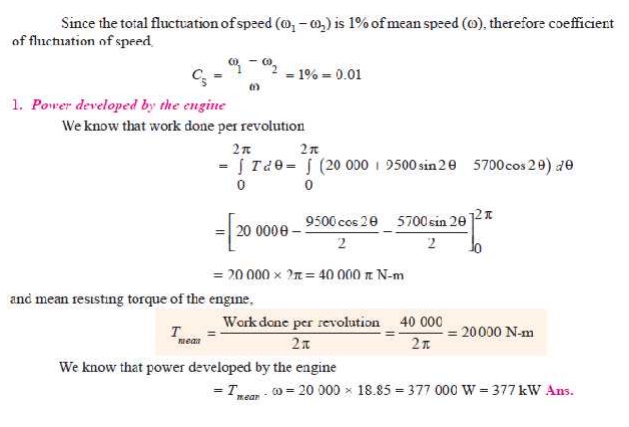
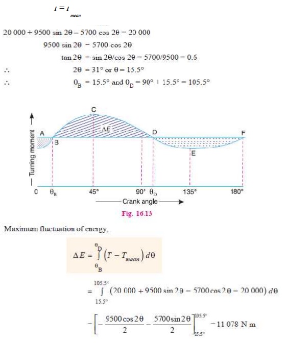
Q. The turning moment curve for an engine is
represented by the equation, T = (20 000 + 9500 sin 2╬Ė ŌĆō 5700 cos 2╬Ė ) N-m, where ╬Ė is the angle moved by the crank from inner dead
centre. If the resisting torque is constant, find:
1. Power developed by the engine ; 2. Moment of inertia of flywheel in
kg-m2, if the total fluctuation
of speed is not exceed 1% of mean speed which is 180 r.p.m; and 3. Angular acceleration of the flywheel
when the crank has turned through 45┬░ from inner dead centre.
Solution.
Given : T
= (20 000 + 9500 sin 2╬Ė ŌĆō 5700 cos 2╬Ė ) N-m ; N = 180 r.p.m. or
Žē = 2ŽĆ ├Ś 180/60
= 18.85 rad/s
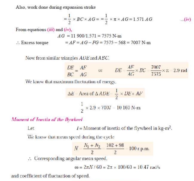
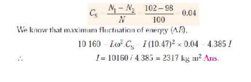
2. Moment
of inertia of the flywheel
Let I = Moment of inertia of the flywheel in kg-m2.
The
turning moment diagram for one stroke (i.e.
half revolution of the crankshaft) is shown in Fig. 16.13. Since at points B and D, the torque exerted on the crankshaft is equal to the mean
resisting torque on the flywheel, therefore,
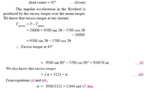
3. Angular acceleration of the flywheel
Let ╬▒ = Angular acceleration of the flywheel, and ╬Ė = Angle turned by the crank from inner
DIMENSIONS OF THE FLYWHEEL RIM
Consider a
rim of the flywheel as shown in Fig. 16.17.
Let D = Mean diameter of rim in metres,
R = Mean
radius of rim in metres,
A =
Cross-sectional area of rim in m2,
Žü =
Density of rim material in kg/m3,
N = Speed
of the flywheel in r.p.m.,
Žē = Angular velocity of the flywheel in rad/s,
v = Linear velocity at the mean
radius in m/s

Žā = Tensile stress or hoop stress in N/m2 due to the
centrifugal force.
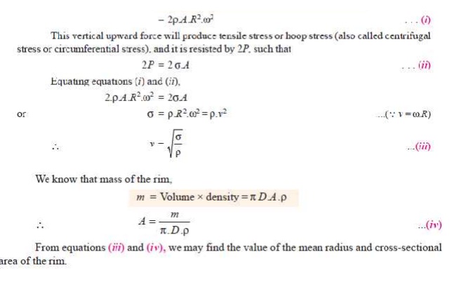
Consider a small element of the rim as shown shaded in Fig. 16.17. Let
it subtends an angle ╬┤╬Ė at the centre of the flywheel.
Volume of the small element
= A ├Ś R.╬┤╬Ė Ōł┤ Mass of the small element
dm = Density ├Ś volume = Žü .A .R.╬┤╬Ė
and
centrifugal force on the element, acting radially outwards, dF =
dm.Žē 2.R = Žü .A .R2.Žē 2.╬┤╬Ė
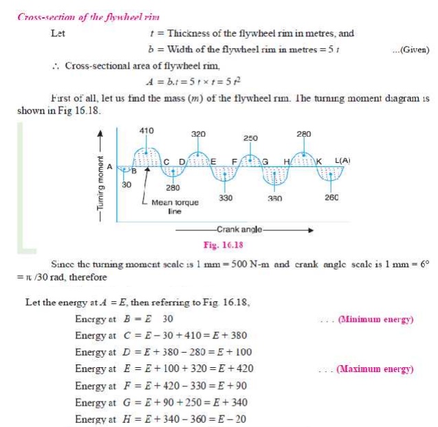
Q.The turning moment diagram for a multi-cylinder
engine has been drawn to a scale of 1 mm to 500 N-m torque and 1 mm to 6┬░
of crank displacement. The intercepted areas between output torque curve and
mean resistance line taken in order from one end, in sq. mm are ŌĆō 30, + 410, ŌĆō
280, + 320, ŌĆō 330, + 250, ŌĆō 360, + 280, ŌĆō 260 sq. mm, when the engine is
running at 800 r.p.m.The engine has a stroke of 300 mm and the fluctuation of
speed is not to exceed ┬▒ 2% of the mean speed. Determine a suitable diameter
and cross-section of the flywheel rim for a limiting value of the safe
centrifugal stress of 7 MPa. The material density may be assumed as 7200 kg/m3.
The width of the rim is to be 5 times the thickness.
Solution. Given : N = 800 r.p.m. or Žē = 2ŽĆ ├Ś 800 / 60 = 83.8 rad/s; *Stroke = 300 mm ; Žā = 7 MPa =
7 ├Ś 10 6 N/m2 ; Žü = 7200
kg/m3
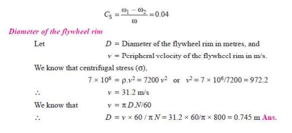
Since the fluctuation of speed is ┬▒ 2% of mean speed, therefore total fluctuation of speed,
Žē 1 ŌĆō Žē 2 = 4% Žē = 0.04 Žē
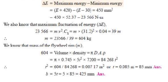
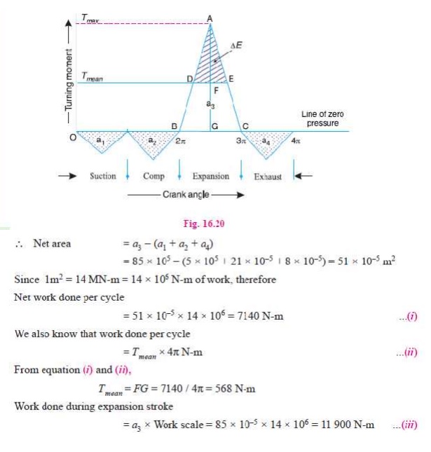
Q. The turning moment diagram of a four stroke engine may be assumed for the sake of simplicity to be represented by four triangles in each stroke. The areas of these triangles are as follows: Suction stroke = 5 ├Ś 10 ŌĆō5 m2; Compression stroke = 21 ├Ś 10 ŌĆō5 m2; Expansion stroke = 85 ├Ś 10 ŌĆō5 m2; Exhaust stroke = 8 ├Ś 10 ŌĆō5 m2.
All the areas excepting expression stroke are negative. Each m2 of area represents 14 MN-m of work.
Assuming the resisting torque to be constant, determine
the moment of inertia of the flywheel to keep the speed between 98 r.p.m. and
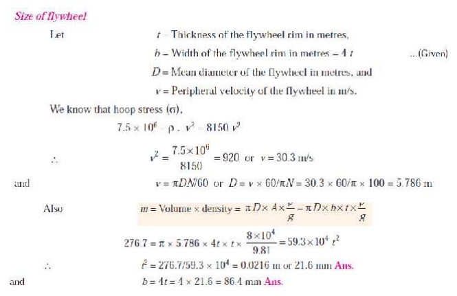
102 r.p.m. Also find the size of a rim-type flywheel based on the minimum
material criterion, given that density of flywheel material is 8150 kg/m3
; the allowable tensile stress of the flywheel material is 7.5 MPa. The rim
cross-section is rectangular, one side being four times the length of the
other.
Solution. Given: a1 = 5 ├Ś 10 ŌĆō5 m2; a2
= 21 ├Ś 10 ŌĆō5 m2; a3 = 85 ├Ś 10 ŌĆō5 m2; a4 = 8 ├Ś 10 ŌĆō5 m2; N2 = 98 r.p.m.; N1 = 102 r.p.m.; Žü = 8150 kg/m3; Žā = 7.5 MPa
= 7.5 ├Ś 10 6 N/m2
FLYWHEEL IN PUNCHING PRESS
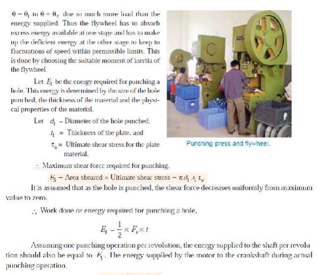
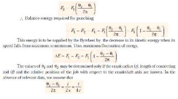

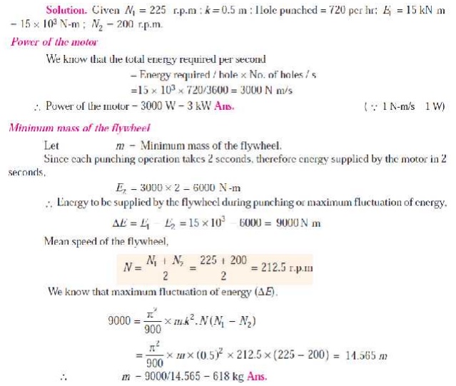
Q. A punching press is driven by a constant torque
electric motor. The press is provided with a flywheel that rotates at maximum speed of
225 r.p.m. The radius of gyration of the flywheel is 0.5 m. The press punches
720 holes per hour; each punching operation takes 2 second and requires 15 kN-m
of energy. Find the power of the motor and the minimum mass of the flywheel if
speed of the same is not to fall below 200 r. p. m.
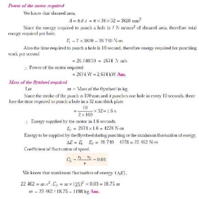
Q. A machine punching 38 mm holes in 32 mm thick
plate requires 7 N -m of energy per sq. mm of sheared area, and punches one hole in
every 10 seconds. Calculate the power of the motor required. The mean speed of
the flywheel is 25 metres per second. The punch has a stroke of 100 mm.
Find the mass of the flywheel required, if the
total fluctuation of speed is not to exceed 3% of the mean speed. Assume that
the motor supplies energy to the machine at uniform rate.
Solution. Given : d = 38 mm ; t = 32 mm ; E1 = 7 N-m/mm2 of sheared area ; v
= 25 m/s ; s = 100 mm ; v1 ŌłÆ v2 = 3% v = 0.03 v
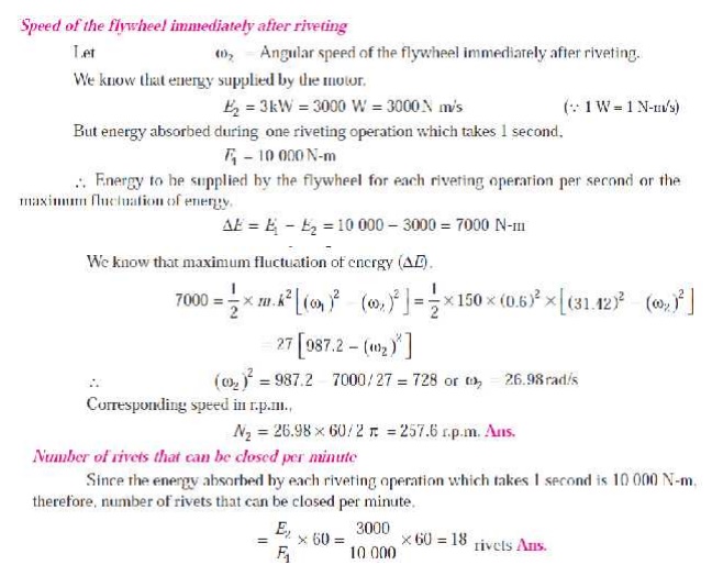
Q. A riveting machine is driven by a constant
torque 3 kW motor. The moving parts including the flywheel are equivalent to 150 kg
at 0.6 m radius. One riveting operation takes 1 second and absorbs 10 000 N-m
of energy. The speed of the flywheel is 300 r.p.m. before riveting. Find the
speed immediately after riveting. How many rivets can be closed per minute?
Solution. Given : P = 3 kW ; m
= 150 kg ; k = 0.6 m ; N1 = 300 r.p.m. or Žē1 = 2ŽĆ ├Ś 300/60 = 31.42 rad/s
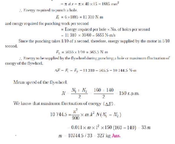
Q. A punching press is required to punch 40 mm
diameter holes in a plate of 15 mm thickness at the rate of 30 holes per minute. It
requires 6 N-m of energy per mm 2 of sheared area. If the punching
takes 1/10 of a second and the r.p.m. of the flywheel varies from 160 to 140,
determine the mass of the flywheel having radius of gyration of 1 metre.
Solution. Given: d = 40 mm; t
= 15 mm; No. of holes = 30 per
min.; Energy required = 6 N-m/mm2;
Time = 1/10 s = 0.1 s; N1 = 160
r.p.m.; N2 = 140 r.p.m.; k = 1m
We know
that sheared area per hole
CAM DYNAMICS:
Mechanism
provides a non-linear I/O relationship. Different mechanism like single or
multi-degree of freedom, intermittent motion mechanisms and linkages etc. have
different I/O Relationship. When we can not obtain a certain functions from the
well known mechanisms, we use a cam mechanism. It is a one degree of freedom
mechanism of two moving links. One is cam and the other is follower.
Rigid and elastic body cam system.
Analysis of eccentric cam
Problems on Cam ŌĆōfollower system.
Related Topics