Chapter: Mechanical : Metrology and Measurements : Concepts of Measurement
Introduction to Dimensional And Geometric Tolerance
INTRODUCTION TO
DIMENSIONAL AND GEOMETRIC TOLERANCE
General Aspects
In the design and
manufacture of engineering products a great deal of attention has to be paid to
the mating, assembly and fitting of various components. In the early days of
mechanical engineering during the nineteenth century, the majority of such components
were actually mated together, their dimensions being adjusted until the
required type of fit was obtained. These methods demanded craftsmanship of a
high order and a great deal of very fine work was produced. Present day
standards of quantity production, interchangeability, and continuous assembly
of many complex compounds, could not exist under such a system, neither could
many of the exacting design requirements of modern machines be fulfilled
without the knowledge that certain dimensions can be reproduced with precision
on any number of components. Modern mechanical production engineering is based
on a system of limits and fits, which while not only itself ensuring the
necessary accuracies of manufacture, forms a schedule or specifications to
which manufacturers can adhere.
In
order that a system of limits and fits may be successful, following conditions
must
be fulfilled:
1. The
range of sizes covered by the system must be sufficient for most purposes.
2. It
must be based on some standards; so that everybody understands alike and a
given dimension has the same meaning at all places.
3. For
any basic size it must be possible to select from a carefully designed range of
fit the most suitable one for a given application.
4. Each
basic size of hole and shaft must have a range of tolerance values for each of
the different fits.
5. The
system must provide for both unilateral and bilateral methods of applying the
tolerance.
6. It
must be possible for a manufacturer to use the system to apply either a
hole-based or a shaft-based system as his manufacturing requirements may need.
7. The
system should cover work from high class tool and gauge work where very wide
limits of sizes are permissible.
Nominal Size and Basic
Dimensions
Nominal size: A
'nominal size' is the size which is used for purpose of general identification.
Thus the nominal size of a hole and shaft assembly is 60 mm, even though the
basic size of the hole may be60 mm and the basic size of the shaft 59.5 mm.
Basic dimension: A
'basic dimension' is the dimension, as worked out by purely design
considerations. Since the ideal conditions of producing basic dimension, do not
exist, the basic dimensions can be treated as the theoretical or nominal size,
and it has only to be approximated. A study of function of machine part would
reveal that it is unnecessary to attain perfection because some variations in
dimension, however small, can be tolerated size of various parts. It is, thus,
general practice to specify a basic dimension and indicate by tolerances as to
how much variation in the basic dimension can be tolerated without affecting
the functioning of the assembly into which this part will be used.
Definitions
The
definitions given below are based on those given in IS: 919
Shaft: The
term shaft refers not only to diameter of a circular shaft to any external
dimension on a component.
Hole: This
term refers not only to the diameter of a circular hole but to any internal
dimension on a component.
Basics
of Fit
A fit or limit system consists of a
series of tolerances arranged to suit a specific range of sizes and functions,
so that limits of size may. Be selected and given to mating components to
ensure specific classes of fit. This system may be arranged on the following
basis:
1. Hole
basis system
2. Shaft
basis system.

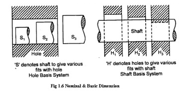
Hole
basis system:
'Hole basis system' is one in which the
limits on the hole are kept constant and the variations necessary to obtain the
classes of fit are arranged by varying those on the shaft.
Shaft
basis system:
'Shaft basis system' is one in which the limits on
the shaft are kept constant and the variations necessary to obtain the classes
of fit are arranged by varying the limits on the holes. In present day
industrial practice hole basis system is used because a great many holes are
produced by standard tooling, for example, reamers drills, etc., whose size is
not adjustable. Subsequently the shaft sizes are more readily variable about
the basic size by means of turning or grinding operations. Thus the hole basis
system results in considerable reduction in reamers and other precision tools
as compared to a shaft basis system because in shaft basis system due to
non-adjustable nature of reamers, drills etc. great variety (of sizes) of these
tools are required for producing different classes of holes for one class of
shaft for obtaining different fits.
Systems of Specifying
Tolerances
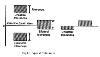
The tolerance or the error permitted in manufacturing
a particular dimension may be allowed to vary either on one side of the basic
size or on either side of the basic size. Accordingly two systems of specifying
tolerances exit.
1. Unilateral
system
2. Bilateral
system.
In the unilateral
system, tolerance is applied only in one direction
+ 0.04 -0.02
Examples: 40.0
or 40.0
+ 0.02 -0.04

In the bilateral system
of writing tolerances, a dimension is permitted to vary in two directions.
+ 0.02 Examples: 40.0
- 0.04
Related Topics