Chapter: Digital Electronics : Combinational Circuits
Important Short Questions and Answers: Digital Electronics - Combinational Circuits
COMBINATIONAL CIRCUITS
1
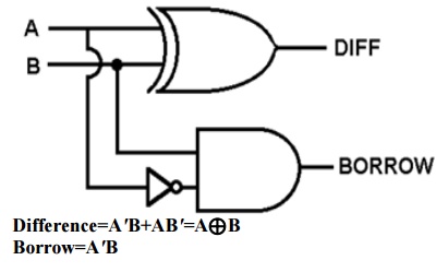
Write an expression for borrow and
difference in a full subtractor circuit.
Difference=A′B+AB′=A⊕B Borrow=A′B
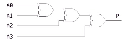
2
Draw the circuits diagram for 4-bit
odd parity generator.
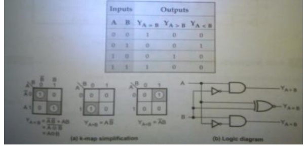
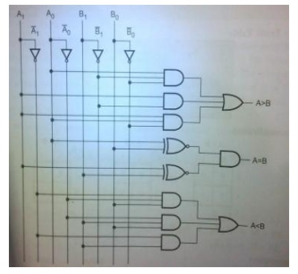
3. Design a single bit magnitude comparator to
compare two words A and B.
4
What is an encoder?
An
encoder has 2n input lines and n output lines. In encoder the output
lines generate the binary code corresponding to the input value.
5
List few applications of multiplexer.
·
Data
Selector.
·
Implement
combinational logic circuit.
·
Time
multiplexing systems
·
Frequency
multiplexing systems.
·
D/A and
A/D converter
·
Data
acquisition systems.
6 Design a half subtractor using basic gates.
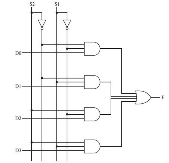
7 Draw the logic diagram of a 4 line to 1 line multiplexer.
8
What is priority Encoder?
A
priority encoder is an encoder circuit that includes the priority function. In
priority encoder, if 2 or more inputs are equal to 1 at the same time, the
input having the highest priority will take precedence.
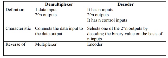
9 Write down the difference between demultiplexer and decoder.
10
Give the logic expression for sum and carry in
full adder circuit.
Sum= (A⊕B)⊕Cin Carry=AB+BCin+A Cin
11
Give examples for combinational circuit.
i.
Adders
ii.
Subtractors
iii.
Multiplexers
iv.
Demultiplexers
v.
Encoders
vi.
Decoders
12
Draw the logic circuit of a 2-bit comparator.
13
Suggest a solution to overcome the limitation
on the speed of an adder.
It is
possible to increase speed of adder by eliminating inter-stage carry delay.
This method utilizes logic gates to look at the lower-order bits of the augend
and addend to see if a higher-order carry is to be generated.
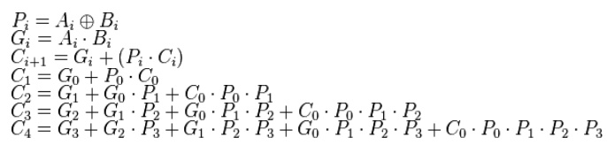
14
Relate carry generate, Carry propagate, Sum and
Carry-out of a Carry look a head adder.
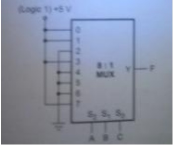
15 Realize the Boolean function using
appropriate multiplexer F(A,B,C)= Σ (0,1,3,7)
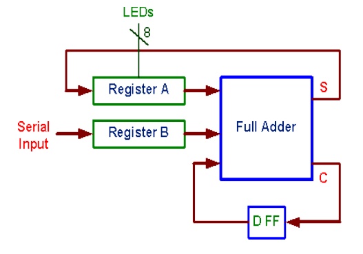
16 Compare the performance of binary serial and
parallel adders.
Serial Adder:
·
Serial
adder uses shift registers
·
The
serial adder requires only one full adder circuit
·
The
serial adder is a sequential circuit
·
Time
required for addition depends on the number of bits
·
It is
slower
parallel adder:
·
Parallel
adder uses registers with parallel load capacity
·
It is
faster
·
Time
required for addition does not depend on number of bits
·
Excluding
the registers, the parallel adder is a purely combinational circuit
17
Design of three bit parity generator.
Odd
parity generator:

18 Draw the logic diagram of serial adder.
19
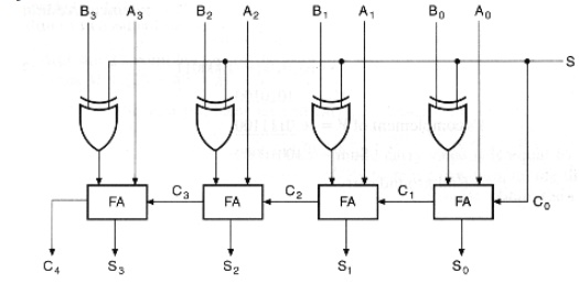
Construct a two-4-bit parallel adder/subtractor
using Full Adders and XOR gates.
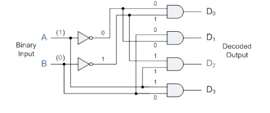
20
Convert a two-to-four line decoder with enable
input to 1X4 Demultiplexer.
Related Topics