Chapter: Transmission and Distribution : Structure of Power System
Generation, Transmission and Distribution of Electric Power
GENERATION, TRANSMISSION AND DISTRIBUTION OF ELECTRIC POWER
1. INTRODUCTION
In this lesson a brief idea of a modern power system is outlined. Emphasis is given to create a clear mental picture of a power system to a beginner of the course Electrical Technology. As consumers, we use electricity for various purposes such as:
1. Lighting, heating, cooling and other domestic electrical appliances used in home.
2. Street lighting, flood lighting of sporting arena, office building lighting, powering PCs etc.
3. Irrigating vast agricultural lands using pumps and operating cold storages for various agricultural products.
4. Running motors, furnaces of various kinds, in industries.
5. Running locomotives (electric trains) of railways.
The list above is obviously not exhaustive and could be expanded and categorized in detail further. The point is, without electricity, modern day life will simply come to a stop. In fact, the advancement of a country is measured by the index per capita consumption of electricity – more it is more advanced the country is.

2. BASIC IDEA OF GENERATION
Prior to the discovery of Faraday’s Laws of electromagnetic discussion, electrical power was available from batteries with limited voltage and current levels. Although complicated in construction, D.C generators were developed first to generate power in bulk. However, due to limitation of the D.C machine to generate voltage beyond few hundred volts, it was not economical to transmit large amount of power over a long distance. For a given amount of power, the current magnitude (I = P/V), hence section of the copper conductor will be large. Thus generation, transmission and distribution of d.c power were restricted to area of few kilometer radius with no interconnections between generating plants. Therefore, area specific generating stations along with its distribution networks had to be used.
Examples
Thermal, hydel & nuclear power stations In this section we briefly outline the basics of the three most widely found generating stations – thermal, hydel and nuclear plants in our country and elsewhere.
Thermal plant
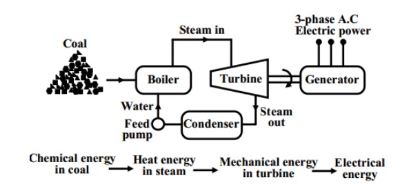
We have seen in the previous section that to generate voltage at 50 Hz we have to run the generator at some fixed rpm by some external agency. A turbine is used to rotate the generator. Turbine may be of two types, namely steam turbine and water turbine. In a thermal power station coal is burnt to produce steam which in turn, drives the steam turbine hence the generator (turbo set). In figure the elementary features of a thermal power plant is shown. In a thermal power plant coil is burnt to produce high temperature and high pressure steam in a boiler. The steam is passed through a steam turbine to produce rotational motion. The generator, mechanically coupled to the turbine, thus rotates producing electricity. Chemical energy stored in coal after a couple of transformations produces electrical energy at the generator terminals as depicted in the figure. Thus proximity of a generating station nearer to a coal reserve and water sources will be most economical as the cost of transporting coal gets reduced. In our country coal is available in abundance and naturally thermal power plants are most popular. However, these plants pollute the atmosphere because of burning of coals.

Stringent conditions (such as use of more chimney heights along with the compulsory use of electrostatic precipitator) are put by regulatory authorities to see that the effect of pollution is minimized. A large amount of ash is produced every day in a thermal plant and effective handling of the ash adds to the running cost of the plant. Nonetheless 57% of the generation in out country is from thermal plants. The speed of alternator used in thermal plants is 3000 rpm which means 2-pole alternators are used in such plants.
Transmission
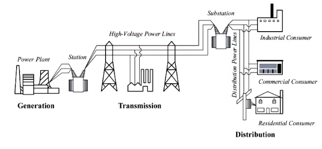
The power plants typically produce 50 cycle/second (Hertz), alternating-current (AC) electricity with voltages between 11kV and 33kV. At the power plant site, the 3-phase voltage is stepped up to a higher voltage for transmission on cables strung on cross-country towers. High voltage (HV) and extra high voltage (EHV) transmission is the next stage from power plant to transport A.C. power over long distances at voltages like; 220 kV & 400 kV. Where transmission is over 1000 kM, high voltage direct current transmission is also favoured to minimize the losses. Sub-transmission network at 132 kV, 110 kV, 66 kV or 33 kV constitutes the next link towards the end user. Distribution at 11 kV / 6.6 kV / 3.3 kV constitutes the last link to the consumer, who is connected directly or through transformers depending upon the drawl level of service. The transmission and distribution network include sub-stations, lines and distribution transformers. High voltage transmission is used so that smaller, more economical wire sizes can be employed to carry the lower current and to reduce losses. Sub-stations, containing step-down transformers, reduce the voltage for distribution to industrial users. The voltage is further reduced for commercial facilities. Electricity must be generated, as and when it is needed since electricity cannot be stored virtually in the system.
Distribution
There is no difference between a transmission line and a distribution line except for the voltage level and power handling capability. Transmission lines are usually capable of transmitting large quantities of electric energy over great distances. They operate at high voltages. Distribution lines carry limited quantities of power over shorter distances. Voltage drops in line are in relation to the resistance and reactance of line, length and the current drawn. For the same quantity of power handled, lower the voltage, higher the current drawn and higher the voltage drop. The current drawn is inversely proportional to the voltage level for the same quantity of power handled. The power loss in line is proportional to resistance and square of current. (i.e. PLOSS=I2R). Higher voltage transmission and distribution thus would help to minimize line voltage drop in the ratio of voltages, and the line power loss in the ratio of square of voltages. For instance, if distribution of power is raised from 11 kV to 33 kV, the voltage drop would be lower by a factor 1/3 and the line loss would be lower by a factor (1/3)2 i.e., 1/9. Lower voltage transmission and distribution also calls for bigger size conductor on account of current handling capacity needed.
Related Topics