Chapter: Transmission and Distribution : Structure of Power System
Connection Schemes of Distribution System
CONNECTION SCHEMES OF DISTRIBUTION SYSTEM
All distribution of electrical energy is done by constant voltage system. In practice, the following distribution circuits are generally used :
( i) Radial System.
In this system, separate feeders radiate from a single substation and feed the distributors at one end only. Fig. shows a single line diagram of a radial system for d.c. distribution where a feeder OC supplies a distributor A B at point A . Obviously, the distributor is fed at one end only i.e., point A is this case. Fig ( ii) shows a single line diagram of radial system for a.c. distribution. The radial system is employed only when power is generated at low voltage and the substation is located at the centre of the load.
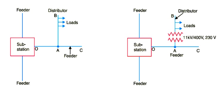
This is the simplest distribution circuit and has the lowest initial cost. However, it suffers from the following drawbacks :
( a) The end of the distributor nearest to the feeding point will be heavily loaded.
( b) The consumers are dependent on a single feeder and single distributor. Therefore, any fault on the feeder or distributor cuts off supply to the consumers who are on the side of the fault away from the substation.
( c) The consumers at the distant end of the distributor would be subjected to serious voltage fluctuations when the load on the distributor changes.
Due to these limitations, this system is used for short distances only.
( ii) Ring main system.
In this system, the primaries of distribution transformers form a loop. The loop circuit starts from the substation bus-bars, makes a loop through the area to be served, and returns to the substation. Fig. 12.9 shows the single line diagram of ring main system for a.c. distribution where substation supplies to the closed feeder LMNOPQRS.
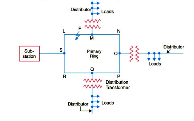
The distributors are tapped from different points M, O and Q of the feeder through distribution transformers. The ring main system has the following advantages :
( a) There are less voltage fluctuations at consumer’s terminals.
( b) The system is very reliable as each distributor is fed via *two feeders. In the event of fault on any section of the feeder, the continuity of supply is maintained. For example, suppose that fault occurs at any point F of section SLM of the feeder. Then section SLM of the feeder can be isolated for repairs and at the same time continuity of supply is maintained to all the consumers via the feeder SRQPONM.
( iii) Interconnected system.
When the feeder ring is energised by two or more than two generating stations or substations, it is called inter-connected system. Fig. 12.10 shows the single line diagram of interconnected system where the closed feeder ring ABCD is supplied by two substations S and S at points D and C respectively.
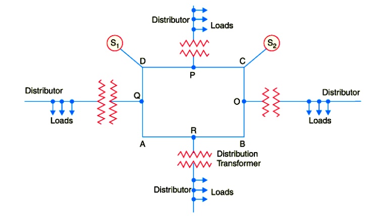
Distributors are connected to points O, P, Q and R of the feeder ring through distribution transformers. The interconnected system has the following advantages :
( a) It increases the service reliability.
( b) Any area fed from one generating station during peak load hours can be fed from the other generating station. This reduces reserve power capacity and increases efficiency of the system.
Related Topics