Chapter: Transmission and Distribution : Structure of Power System
EHVAC and HVDC Transmission System
EHVAC and HVDC Transmission System
Development of EHV transmission systems
EHVAC
The first 735 kV system was commissioned in Canada in 1965. Since then, voltage levels up to 765 kV have been introduced in Russia with neighboring countries, U.S.A, South Africa, Brazil, Venezuela and South Korea. The general trend of 800 kV investments is indicated in the diagram, which shows the total capacity of power transformers and generator step-up transformers for 800 kV delivered by ABB. Since the 90’s, the investments in 800 kV systems have been much lower compared to the 70’s and 80’s. However, plans are under way for future introduction of 800 kV in India and China. The planned introductions of voltages in the UHV range, i.e. 1000 kV and above, have been cancelled or postponed in several countries. e.g. Russia, Italy and U.S.A. Future 1000 kV lines are only considered in Japan.
HVDC
The first HVDC system for ± 500 kV and above was the Cabora Bassa project, commissioned in 1979. The Brasilian Itaipu project is the only HVDC system operating at ±600 kV so far. The major HVDC investments at these voltage levels were made in the late 80’s and early 90’s. However, an increasing interest in high-capacity HVDC links have been noted in recent years, as seen from the diagram, which shows all HVDC projects for ±500 kV and above. The need for higher voltage levels can be anticipated for HVDC projects in the near future, especially when the transmission line is more than 1000 km long. From a technical point of view, there are no special obstacles against higher DC voltages. Present solutions are extendable to e.g. ±800 kV when the need arises. The need for higher voltage levels can be anticipated for HVDC projects in the near future, especially when the transmission line is more than 1000 km long. From a technical point of view, there are no special obstacles against higher DC voltages. Present solutions are extendable to e.g. ±800 kV when the need arises.
Design aspects for AC DC transmission lines
The general design criteria for AC and DC transmission lines can be divided into electrical and mechanical aspects, both having considerable effects on the investment and operation costs. The power transmission capacity determines the voltage level and the number of parallel circuits, which has a great influence on the investment costs. Other aspects are emergency loading capability and reactive power compensation of AC lines. The power losses affects mainly the operating costs and should therefore be optimized with regard to investment cost of the line conductors at the given voltage level. The insulation performance is determined by the overvoltage levels, the air clearances, the environmental conditions and the selection of insulators. The requirements on the insulation performance affect mainly the investment costs for the towers. The corona performance influences heavily on the design of the conductor bundles and, subsequently, on the mechanical forces on the towers from wind and ice loading of the conductors. Any constraints on the electromagnetic fields at the ground level will, however, primarily influence the costs for the right-of-way. The mechanical loading, and hence the investment cost of towers, insulators and conductors, depends mainly on the design of the conductor bundles and the climatic conditions.
1. MERITS & DEMERITS OF HVDC
Merits of HVDC
Undersea cables, where high capacitance causes additional AC losses. (e.g., 250 km Baltic Cable between Sweden and Germany),
Endpoint-to-endpoint long-haul bulk power transmission without intermediate.
Increasing the capacity of an existing power grid in situations where additional wires are difficult or expensive to install
Power transmission and stabilization between unsynchronized AC distribution systems.
Connecting a remote generating plant to the distribution grid, for example Nelson River Bipoler.
Stabilizing a predominantly AC power-grid, without increasing prospective short circuit current.
Reducing line cost. HVDC needs fewer conductors as there is no need to support multiple phases. Also, thinner conductors can be used since HVDC does not suffer from the skin effect.
Facilitate power transmission between different countries that use AC at differing voltages and/or frequencies.
Synchronize AC produced by renewable energy sources.
Demerits
Circuit breaking Is difficult in D.C circuits, therefore the coast of dc circuit is high.
D.C system does not have step up or step down transformers to change the voltage level.
The coast of converter station is very high. Both ac and dc harmonics are generated. System control stability is quite difficult.
2. ECONOMICAL COMPARISION EHVAC and HVDC
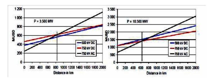
The trend of power electronic components, for use in the main circuit of an HVDC transmission, being developed means that the relative cost of HVDC transmissions is reduced as the components become cheaper as a result of continuing innovative technological developments. Thus a large converter station with a cost of 50 USD/kW is today cheaper in current dollars compared with the situation 20 years ago. The dc line is less costly compared with an 800 kV ac line. On the other hand, the converter station cost offsets the gain in reduced cost of the transmission line. Thus a short line is cheaper with ac transmission, while a longer line is cheaper with dc.
In a general comparison of HVDC vs. EHVAC power transmission, the design of the transmission lines and the related investment costs are of great importance. The aim of this paper has been to focus on the differences in the design of line insulation and conductor configuration, and its influence on the mechanical loads. For the line insulation, air clearance requirements are more critical with EHVAC due to the nonlinear behavior of the switching overvoltage withstand. The corona effects are more pronounced at AC voltage, therefore, larger conductor bundles are needed at higher system voltages. The altitude effects are more important to HVDC lines, since the lightning overvoltage withstand is the most sensitive insulation parameter with regard to air density. The mechanical load on the tower is considerably lower with HVDC due to less number of sub conductors required to fulfill the corona noise limits. The high transmission capacity of the HVDC lines, combined with lower requirements on conductor bundles and air clearances at the higher voltage levels, makes the HVDC lines very cost efficient compared to EHVAC lines. The cost advantage is even more pronounced at the highest voltage levels.
Related Topics