Chapter: Transmission and Distribution : Structure of Power System
Distribution Systems
DISTRIBUTION SYSTEMS - GENERAL
The electrical energy produced at the generating station is conveyed to the consumers through a network of transmission and distribution systems. It is often difficult to draw a line between the transmission and distribution systems of a large power system. It is impossible to distinguish the two merely by their voltage because what was considered as a high voltage a few years ago is now considered as a low voltage. In general, distribution system is that part of power system which distributes power to the consumers for utilization.
The transmission and distribution systems are similar to man’s circulatory system. The trans- mission system may be compared with arteries in the human body and distribution system with capillaries. They serve the same purpose of the ultimate consumer in the city with the life-giving blood of civilization–electricity. In this chapter, we shall confine our attention to the general introduction to distribution.
1. Distribution System
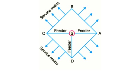
That part of power system which distributes electric power for local use is known as distribution system. In general, the distribution system is the electrical system between the substation fed by the Transmission system and the consumer’s meters. It generally consists of feeders, distributors, and service mains. Fig. 12.1 shows the single line diagram of a typical low tension distribution system.
i) Feeders
A feeder is a conductor which connects the sub-station (or localized generating station) to the area where power is to be distributed. Generally, no tappings are taken from the feeder so that current in it remains the same throughout. The main consideration in the design of a feeder is the current carrying capacity.
(ii)Distributor
A distributor is a conductor from which tappings are taken for supply to the consumers. In Fig. AB, BC, CD and DA are the distributors. The current through a distributor is not constant because tappings are taken at various places along its length. While designing a distributor, voltage drop along its length is the main consideration since the statutory limit of voltage variations is ± 6% of rated value at the consumers’ terminals.
(iii) Service mains
A service mains is generally a small cable which connects the distributor to the consumers’ terminals.
2. CLASSIFICATION OF DISTRIBUTION SYSTEMS
A distribution system may be classified according to ;
i)Nature of current
According to nature of current, distribution system may be classified as
(a) d.c. Distribution system
(b) a.c. Distribution system
Now-a-days, a.c. system is universally adopted for distribution of electric power as it is simpler and more economical than direct current method
ii) Type of construction
According to type of construction distribution system may be classified as
(a)Overhead system
(b) Underground system.
The overhead system is generally employed for distribution as it is 5 to 10 times cheaper than the equivalent underground system. In general, the underground system is used at places where overhead con struction is impracticable or prohibited by the local laws
(iii) Scheme of connection
According to scheme of connection, the distribution system may be classified as
(a)Radial system
(b) Ring main system
(c) Inter-connected system
3. AC DISTRIBUTION
Now-a-days electrical energy is generated, transmitted and distributed in the form of alternating cur-rent. One important reason for the widespread use of alternating current in preference to direct current is the fact that alternating voltage can be conveniently changed in magnitude by means of a transformer. Transformer has made it possible to transmit a.c. power at high voltage and utilise it at a safe potential. High transmission and distribution voltages have greatly reduced the current in the conductors and the resulting line losses.
There is no definite line between transmission and distribution according to voltage or bulk capacity. However, in general, the a.c. distribution system is the electrical system between the step- down substation fed by the transmission system and the consumers’ meters. The a.c. distribution system is classified into
i. primary distribution system and
ii. Secondary distribution system.
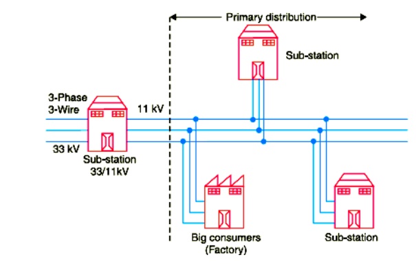
i) Primary distribution system.
It is that part of a.c. distribution system which operates at voltages somewhat higher than general utilization and handles large blocks of electrical energy than the average low-voltage consumer uses. The voltage used for primary distribution depends upon the amount of power to be conveyed and the distance of the substation required to be fed. The most commonly used primary distribution voltages are 11 kV, 6·6 kV and 3·3 kV.
Due to economic considerations, primary distribution is carried out by 3- phase, 3-wire system Fig. shows a typical primary distribution system Electric power from the generating station is transmitted at high voltage to the substation located in or near the city.
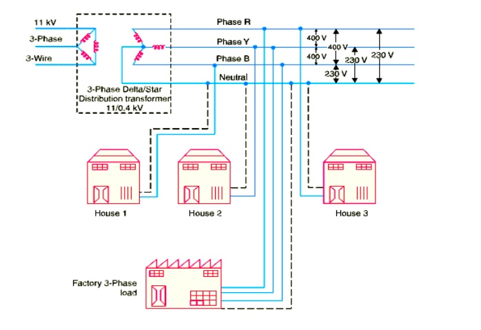
ii) Secondary distribution system
It is that part of a.c. distribution system. The secondary distribution employs 400/230V,3-phase,4wire system. Fig shows a typical secondary distribution system. The primary distribution circuit delivers power to various substations, called distribution sub-stations. The substations are situated near the consumers’ localities and contain step-down transformers. At each distribution substation, the voltage is stepped down to 400Vandpowerisdeliveredby 3-phase,4-wire a.c. system. The voltage between any two phases is 400V and between any phase and neutralize 230V.The single phase domestic loads are connected between any one phase and the neutral, where as 3-phase 400V motor loads are connected across 3- phase lines directly.
4. D.C. DISTRIBUTION
It is a common knowledge that electric power is almost exclusively generated, transmitted and distributed as a.c. However, for certain applications, d.c. supply is absolutely necessary. For instance, d.c. supply is required for the operation of variable speed machinery (d.c. motors), for electro-chemical work and for congested areas where storage battery reserves are necessary. For this purpose, a.c. power is converted into d.c. power at the substation by using converting machinery e.g., mercury arc rectifiers, rotary converters and motor-generator sets. The d.c. supply from the substation may be obtained in the form of
( i) 2-wire
( ii) 3-wire for distribution.
( i) 2-wire d.c. system.
As the name implies, this system of distribution consists of two wires. One is the outgoing or positive wire and the other is the return or negative wire. The loads such as lamps, motors etc. are connected in parallel between the two wires as shown in Fig. 12.4. This system is never used for transmission purposes due to low efficiency but may be employed for distribution of d.c. power.
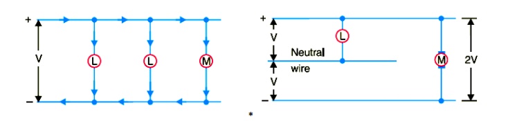
( ii) 3-wire d.c. system.
It consists of two outers and a middle or neutral wire which is earthed at the substation. The voltage between the outers is twice the voltage between either outer and neutral wire as shown in Fig. 12.5. The principal advantage of this system is that it makes available two voltages at the consumer terminals viz., V between any outer and the neutral and 2V between the outers. Loads requiring high voltage ( e.g., motors) are connected across the outers, whereas lamps and heating circuits requiring less voltage are connected between either outer and the neutral. The methods of obtaining 3-wire system are discussed in the following article.
5. OVERHEAD VERSUS UNDERGROUND SYSTEM
The distribution system can be overhead or underground. Overhead lines are generally mounted on wooden, concrete or steel poles which are arranged to carry distribution transformers in addition to the conductors. The underground system uses conduits, cables and manholes under the surface of streets and sidewalks. The choice between overhead and underground system depends upon a num-ber of widely differing factors. Therefore, it is desirable to make a comparison between the two.
( i) Public safety.
The underground system is more safe than overhead system because all distribution wiring is placed underground and there are little chances of any hazard.
( ii) Initial cost.
The underground system is more expensive due to the high cost of trenching, conduits, cables, manholes and other special equipment. The initial cost of an underground system may be five to ten times than that of an overhead system.
( iii) Flexibility.
The overhead system is much more flexible than the underground system. In the latter case, manholes, duct lines etc., are permanently placed once installed and the load expansion can only be met by laying new lines. However, on an overhead system, poles, wires, transformers etc., can be easily shifted to meet the changes in load conditions.
( iv) Faults.
The chances of faults in underground system are very rare as the cables are laid underground and are generally provided with better insulation.
( v) Appearance.
The general appearance of an underground system is better as all the distribution lines are invisible. This factor is exerting considerable public pressure on electric supply companies to switch over to underground system.
( vi) Fault location and repairs.
In general, there are little chances of faults in an underground system. However, if a fault does occur, it is difficult to locate and repair on this system. On an overhead system, the conductors are visible and easily accessible so that fault locations and repairs can be easily made.
( vii) Current carrying capacity and voltage drop.
An overhead distribution conductor has a considerably higher current carrying capacity than an underground cable conductor of the same material and cross-section. On the other hand, underground cable conductor has much lower inductive reactance than that of an overhead conductor because of closer spacing of conductors.
( viii) Useful life.
The useful life of underground system is much longer than that of an overhead system. An overhead system may have a useful life of 25 years, whereas an underground system may have a useful life of more than 50 years.
( ix) Maintenance cost.
The maintenance cost of underground system is very low as compared with that of overhead system because of less chances of faults and service interruptions from wind, ice, lightning as well as from traffic hazards.
( x) Interference with communication circuits.
An overhead system causes electromagnetic interference with the telephone lines. The power line currents are superimposed on speech currents, resulting in the potential of the communication channel being raised to an undesirable level. However, there is no such interference with the underground system.
It is clear from the above comparison that each system has its own advantages and disadvan tages. However, comparative economics ( i.e., annual cost of operation) is the most powerful factor influencing the choice between underground and overhead system. The greater capital cost of underground system prohibits its use for distribution. But sometimes non-economic factors ( e.g., general appearance, public safety etc.) exert considerable influence on choosing underground system. In general, overhead system is adopted for distribution and the use of underground system is made only where overhead construction is impracticable or prohibited by local laws.
6. CONNECTION SCHEMES OF DISTRIBUTION SYSTEM
All distribution of electrical energy is done by constant voltage system. In practice, the following distribution circuits are generally used :
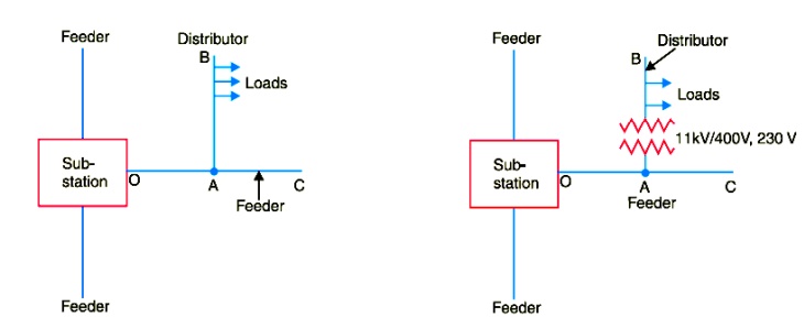
( i) Radial System.
In this system, separate feeders radiate from a single substation and feed the distributors at one end only. Fig. shows a single line diagram of a radial system for d.c. distribution where a feeder OC supplies a distributor A B at point A . Obviously, the distributor is fed at one end only i.e., point A is this case. Fig ( ii) shows a single line diagram of radial system for a.c. distribution. The radial system is employed only when power is generated at low voltage and the substation is located at the centre of the load.
This is the simplest distribution circuit and has the lowest initial cost. However, it suffers from the following drawbacks :
( a) The end of the distributor nearest to the feeding point will be heavily loaded.
( b) The consumers are dependent on a single feeder and single distributor. Therefore, any fault on the feeder or distributor cuts off supply to the consumers who are on the side of the fault away from the substation.
( c) The consumers at the distant end of the distributor would be subjected to serious voltage fluctuations when the load on the distributor changes.
Due to these limitations, this system is used for short distances only.
( ii) Ring main system.
In this system, the primaries of distribution transformers form a loop. The loop circuit starts from the substation bus-bars, makes a loop through the area to be served, and returns to the substation. Fig. 12.9 shows the single line diagram of ring main system for a.c. distribution where substation supplies to the closed feeder LMNOPQRS.
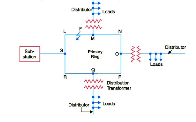
The distributors are tapped from different points M, O and Q of the feeder through distribution transformers. The ring main system has the following advantages :
( a) There are less voltage fluctuations at consumer’s terminals.
( b) The system is very reliable as each distributor is fed via *two feeders. In the event of fault on any section of the feeder, the continuity of supply is maintained. For example, suppose that fault occurs at any point F of section SLM of the feeder. Then section SLM of the feeder can be isolated for repairs and at the same time continuity of supply is maintained to all the consumers via the feeder SRQPONM.
( iii) Interconnected system.
When the feeder ring is energised by two or more than two generating stations or substations, it is called inter-connected system. Fig. 12.10 shows the single line diagram of interconnected system where the closed feeder ring ABCD is supplied by two substations S and S at points D and C respectively.
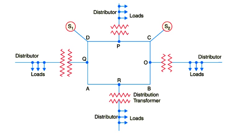
Distributors are connected to points O, P, Q and R of the feeder ring through distribution transformers. The interconnected system has the following advantages :
( a) It increases the service reliability.
( b) Any area fed from one generating station during peak load hours can be fed from the other generating station. This reduces reserve power capacity and increases efficiency of the system.
7. REQUIREMENTS OF A DISTRIBUTION SYSTEM
A considerable amount of effort is necessary to maintain an electric power supply within the requirements of various types of consumers. Some of the requirements of a good distribution system are : proper voltage, availability of power on demand and reliability.
( i) Proper voltage.
One important requirement of a distribution system is that voltage variations at consumer’s terminals should be as low as possible. The changes in voltage are generally caused due to the variation of load on the system. Low voltage causes loss of revenue, inefficient lighting and possible burning out of motors. High voltage causes lamps to burn out permanently and may cause failure of other appliances. Therefore, a good distribution system should ensure that the voltage variations at consumers terminals are within permissible limits. The statutory limit of voltage variations is ± 6% of the rated value at the consumer’s terminals. Thus, if the declared voltage is 230 V, then the highest voltage of the consumer should not exceed 244 V while the lowest voltage of the consumer should not be less than 216 V.
( ii) Availability of power on demand.
Power must be available to the consumers in any amount that they may require from time to time. For example, motors may be started or shut down, lights may be turned on or off, without advance warning to the electric supply company. As electrical energy cannot be stored, therefore, the distribution system must be capable of supplying load demands of the consumers. This necessitates that operating staff must con-tinuously study load patterns to predict in advance those major load changes that follow the known schedules.
( iii) Reliability.
Modern industry is almost dependent on electric power for its operation. Homes and office buildings are lighted, heated, cooled and ventilated by electric power. This calls for reliable service. Unfortunately, electric power, like everything else that is man-made, can never be absolutely reliable. However, the reliability can be improved to a considerable extent by ( a) interconnected system ( b) reliable automatic control system ( c) providing additional reserve facilities.
8. DESIGN CONSIDERATIONS IN DISTRIBUTION SYSTEM
Good voltage regulation of a distribution network is probably the most important factor responsible for delivering good service to the consumers. For this purpose, design of feeders and distributors requires careful consideration.
( i) Feeders.
A feeder is designed from the point of view of its current carrying capacity while the voltage drop consideration is relatively unimportant. It is because voltage drop in a feeder can be compensated by means of voltage regulating equipment at the substation.
( ii) Distributors.
A distributor is designed from the point of view of the voltage drop in it. It is because a distributor supplies power to the consumers and there is a statutory limit of voltage variations at the consumer’s terminals (± 6% of rated value). The size and length of the distributor should be such that voltage at the consumer’s terminals is within the permissible limits.
Related Topics