Chapter: Transmission and Distribution : Structure of Power System
A.C. Distribution -Introduction
A.C. DISTRIBUTION -INTRODUCTION
In the beginning of electrical age, electricity was generated, transmitted and distributed as direct current. The principal disadvantage of d.c. system was that voltage level could not readily be changed, except by the use of rotating machinery, which in most cases was too expensive. With the development of transformer by George Westinghouse, a.c. system has become so predominant as to make d.c. system practically extinct in most parts of the world. The present day large power system has been possible only due to the adoption of a.c. system Now-a-days, electrical energy is generated, transmitted and distributed in the form of alter- nating current as an economical proposition. The electrical energy produced at the power station is transmitted at very high voltages by 3-phase, 3-wire system to step-down sub-stations for distribution. The distribution system consists of two parts viz. primary distribution and secondary distribution. The primary distribution circuit is 3-phase, 3-wire and operates at voltages (3·3 or 6·6 or 11kV) somewhat higher than general utilization levels. It delivers power to the secondary distribution circuit through distribution transformers situated near consumers’ localities. Each distribution transformer steps down the voltage to 400 V and power is distributed to ultimate consumers’ by 400/230 V, 3-phase, 4-wire system. In this chapter, we shall focus our attention on the various aspects of a.c. distribution.
1. A.C. DISTRIBUTION CALCULATIONS
A.C. distribution calculations differ from those of d.c. distribution in the following respects :
( i) In case of d.c. system, the voltage drop is due to resistance alone. However, in a.c. system, the voltage drops are due to the combined effects of resistance, inductance and capacitance.
( ii) In a d.c. system, additions and subtractions of currents or voltages are done arithmetically but in case of a.c. system, these operations are done vectorially.
( iii) In an a.c. system, power factor (p.f.) has to be taken into account. Loads tapped off
form the distributor are generally at different power factors. There are two ways of referring power factor viz
( a) It may be referred to supply or receiving end voltage which is regarded as the reference vector.
( b) It may be referred to the voltage at the load point itself.
There are several ways of solving a.c. distribution problems. However, symbolic notation method has been found to be most convenient for this purpose. In this method, voltages, currents and impedances are expressed in complex notation and the calculations are made exactly as in d.c. distribution.
2. METHODS OF SOLVING A.C. DISTRIBUTION PROBLEMS
In a.c. distribution calculations, power factors of various load currents have to be considered since currents in different sections of the distributor will be the vector sum of load currents and not the arithmetic sum. The power factors of load currents may be given ( i) w.r.t. receiving or sending end voltage or ( ii) w.r.t. to load voltage itself. Each case shall be discussed separately.
( i) Power factors referred to receiving end voltage.
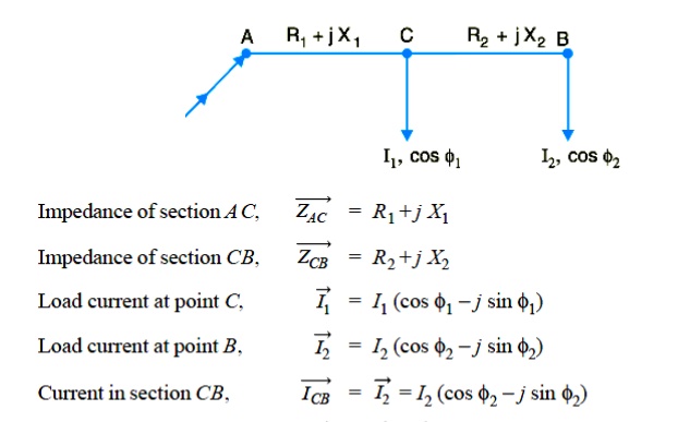
Consider an a.c. distributor A B with concentrated loads of I1 and I2 tapped off at points C and B as shown in Fig. Taking the receiving end voltage VB as the reference vector, let lagging power factors at C and B be cos φ1 and cos φ 2 w.r.t. VB . Let R1 , X1 and R2 , X2 be the resistance and reactance of sections A C and CB of the distributor.
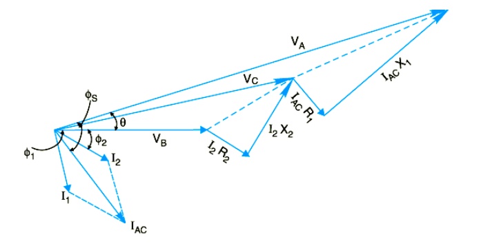
The vector diagram of the a.c. distributor under these conditions is shown in Fig. Here, the receiving end voltage VB is taken as the reference vector. As power factors of loads are given w.r.t. VB , therefore, I1 and I2 lag behind VB by φ1 and φ2 respectively.
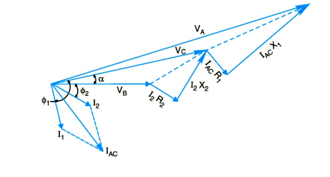
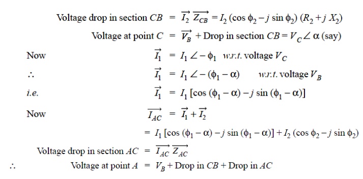
( ii) Power factors referred to respective load voltages.
Suppose the power factors of loads in the previous Fig. are referred to their respective load voltages. Then φ1 is the phase angle between VC and I1and φ2 is the phase angle between VB and I2 . The vector diagram under these conditions is shown in Fig
Related Topics