Chapter: Mechanical : Automobile Engineering : Transmission Systems
Gear Box: Principle of Gearing and Types of Gear Boxes
Gear Box
A gearbox is a mechanical method of transferring energy from
one device to another and is used to increase torque while reducing speed.
Torque is the power generated through the bending or twisting of a solid
material. This term is often used interchangeably with transmission.Located at
the junction point of a power shaft, the gearbox is often used to create a
right angle change in direction, as is seen in a rotary mower or a helicopter.
Each unit is made with a specific purpose in mind, and the gear ratio used is
designed to provide the level of force required. This ratio is fixed and cannot
be changed once the box is constructed. The only possible modification after
the fact is an adjustment that allows the shaft speed to increase, along with a
corresponding reduction in torque.In a situation where multiple speeds are
needed, a transmission with multiple gears can be used to increase torque while
slowing down the output speed. This design is commonly found in automobile
transmissions. The same principle can be used to create an overdrive gear that
increases output speed while decreasing torque.
Principle Of Gearing
Consider a simple 4-gear train. It consists of a driving gear
A on input shaft and a driven gear D on the output shaft. In between the two
gears there are two intermediate gears B, C. Each of these gears are mounted on
separate shaft.We notice that:
Gear A drives Gear B
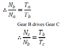
Gear C drives Gear D
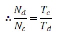
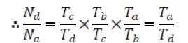
Therefore, the over all speed ratios are:
1.Types of Gear Boxes:
The following types of gear box
are used in automobiles:
·
Sliding Mesh
·
Constant Mesh
·
Synchromesh.
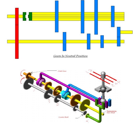
i. Sliding Mesh Gear Box
It
is the simplest gear box. The following figure shows 4-speed gear box in
neutral position.
4 gears
are connected to the lay shaft/counter shaft. A reverse idler gear is mounted
on another shaft and always remains connected to the reverse gear of
countershaft. This “H” shift pattern enables the
driver to select four different
gear ratios and a reverse gear.
Gears in Neutral:
When the engine is running and clutch is engaged the clutch
shaft gear drives the countershaft gear. The countershaft rotates opposite in
direction of the clutch shaft. In neutral position only the clutch shaft gear
is connected to the countershaft gear. Other gears are free and hence the
transmission main shaft is not turning. The vehicle is stationary.

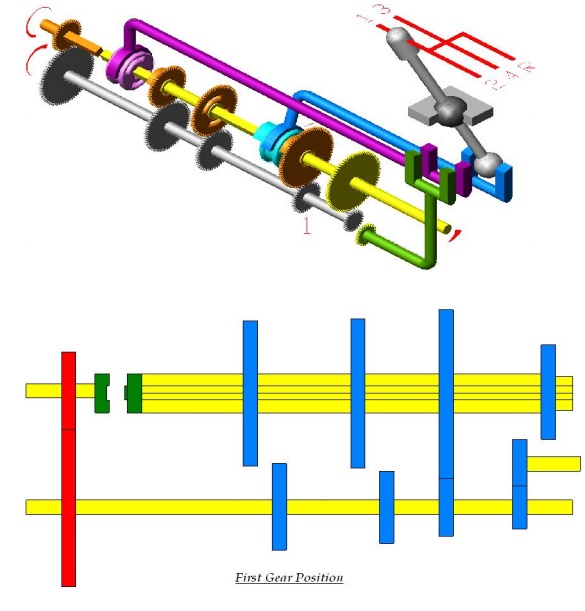
First or low shaft gear:
By operating the gear shift lever the larger gear on the main
shaft is moved along the shaft to mesh with the first gear of the counter
shaft. The main shaft turns in the same direction as that of the clutch shaft.
Since the smaller countershaft is engaged with larger shaft gear a gear
reduction of approximately 4:1 is obtained i.e. the clutch shaft turns 4 times
for each revolution of main shaft.
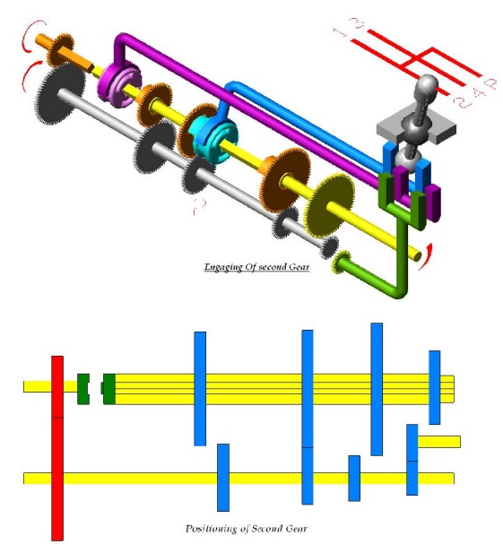
Second speed gear:
By operating the gear shift lever the third gear on the main
shaft is moved along the shaft to mesh with the third gear of the counter
shaft. The main shaft turns in same direction as clutch shaft. A gear reduction
of approximately 3:1is obtained.
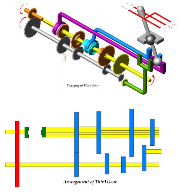
Third speed gear:
By operating the gear shift lever, the second gear of the main
shaft and countershaft are demeshed and then the third gear of the main shaft
are forced axially against the clutch shaft gear. External Teeth on the clutch
shaft gear mesh with the internal teeth in the third and top gear. The main
shaft turns in same direction as clutch shaft. A gear reduction of
approximately 2:1is obtained i.e. the clutch shaft turns 2 times for each
revolution of main shaft.
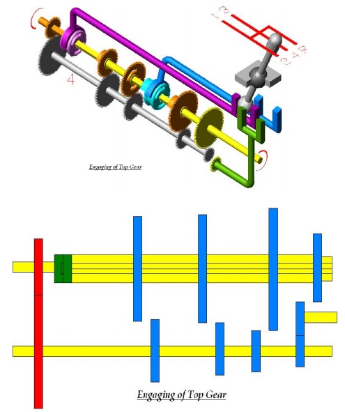
Fourth speed gear/ Top or
High-Speed Gear:
By operating the gear shaft lever the third gears of the main
and countershaft is demeshed and the gears present on the main shaft along with
the shaft is forced axially against the clutch shaft gear. External teeth
present on the main shaft engage with the internal teeth present on the main
shaft. The main shaft turns along with the clutch shaft and a gear ratio of
approximately 1:1 is obtained.
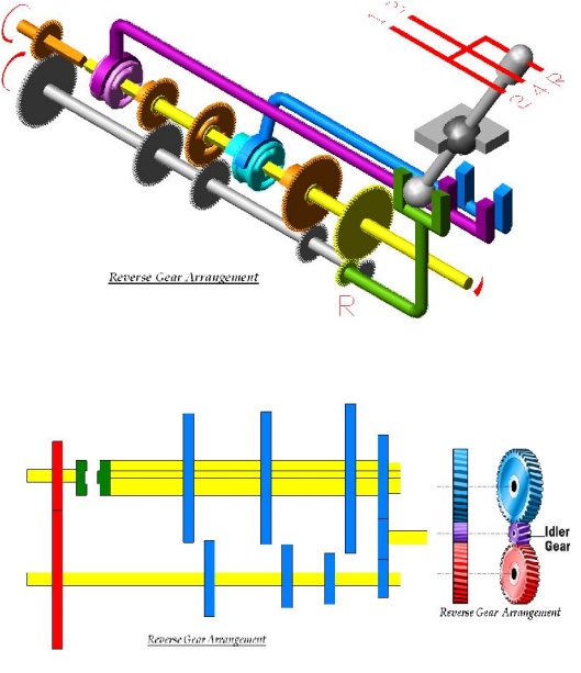
Reverse gear:
By operating the gear shift lever, the last gear present on
the main shaft is engaged with the reverse idler gear. The reverse idler gear
is always in mesh with the counters haft gear. Interposing the idler gear
between the counter-shaft reverse gear and main shaft gear, the main shaft
turns in the direction opposite to the clutch shaft. This reverses the rotation
of the wheels so that the wheel backs.
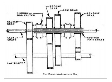
ii.Constant Mesh Gear Box:
In this type of gear box, all gears of the main shaft are in
constant mesh with the corresponding gears of the countershaft (Lay shaft). Two
dog clutches are provided on the main shaft- one between the clutch gear and
the second gear, and the other between the first gear and reverse gear. The
main shaft is splined and all the gears are free on it. Dog clutch can slide on
the shaft and rotates with it. All the gears on the countershaft are rigidly
fixed with it.
When the left hand dog clutch is made to slide to the left by
means of the gear shift lever, it meshes with the clutch gear and the top speed
gear is obtained. When the left hand dog clutch meshes with the second gear,
the second speed gear is obtained. Similarly by sliding the right hand dog
clutch to the left and right, the first speed gear and reverse gear are
obtained respectively. In this gear box because all the gears are in constant
mesh they are safe from being damaged and an unpleasant grinding sound does not
occur while engaging and disengaging them.
iii.Syncromesh Gear Box:
In sliding Mesh Gear box the two meshing gears need to be
revolve at equal peripheral speeds to achieve a jerk less engagement and it is
true for constant mesh gear box in which the peripheral speeds of sliding dog
and the corresponding gear on the output shaft must be equal. The
peripheral
speed is given byWhere d1 and N1 are pitch circle diameter and r.p.m. of gear
and d2 andN2 diameter and r.p.m. of attached dog respectively. Now N1 ≠
N2 since d1 ≠ d2 . Thus there is
a
difference in gear and dog which necessitates double declutching. The driver
has to disengage the clutch twice in quick succession therefore it is referred
as double declutching. There are two steps involved in this process:
The
clutch is disengaged i.e. first declutching and the gear system is placed in
its neutral
position.
Now the clutch is reengaged and acceleration pedal is pressed to adjust the
engine speed according to driver’s judgment.The clutch is
disengaged(i.e. second declutching) again the
appropriate gear is engaged and
then the clutch is reengaged
It is that gear box in which sliding synchronizing units are
provided in place of sliding dog clutches as in case of constant mesh gear box.
With the help of synchronizing unit, the speed of both the driving and driven
shafts is synchronized before they are clutched together through train of
gears. The arrangement of power flow for the various gears remains the same as
in constant mesh gear box. The synchronizer is made of frictional materials.
When the collar tries to mesh with the gear, the synchronizer will touch the
gear first and use friction force to drive the gear to spin at the same speed
as the collar. This will ensure that the collar is meshed into the gear very
smoothly without grinding.Synchromesh gear devices work on the principle that
two gears to be engaged are first bought into frictional contact which
equalizes their speed after which they are engaged readily and smoothly.
The following types of devices
are mostly used in vehicles:
·
Pin Type
·
Synchronizer ring type
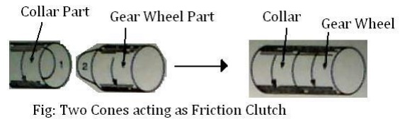
A synchronizing system is used for smooth meshing. Synchromesh
works like a friction clutch. In the following figure two conical surfaces
cone-1 is the part of the collar and the cone-2 is the part of the gear wheel.
Cone1, 2 are revolving at different speeds. While cone-2 is revolving, cone-1
gradually slides into it. Friction slows or speeds up the gear wheel. Finally
both the cones revolve at same speed.
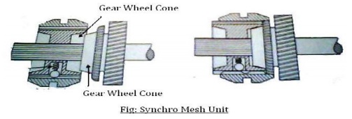
revolving
at different speeds. The internal cone comes in contact with the outer cone of
the gear wheel. Friction slows or speeds up the gear wheel.
And when the collar and gear wheel rotate at same speed the
spring loaded outer ring of the collar is pushed forward. The dog slide
smoothly into mesh without clashing. The collar and gear wheel lock and revolve
at same speed. This the principle of synchromesh.
Related Topics